Toyota Camry (XV70): System Diagram
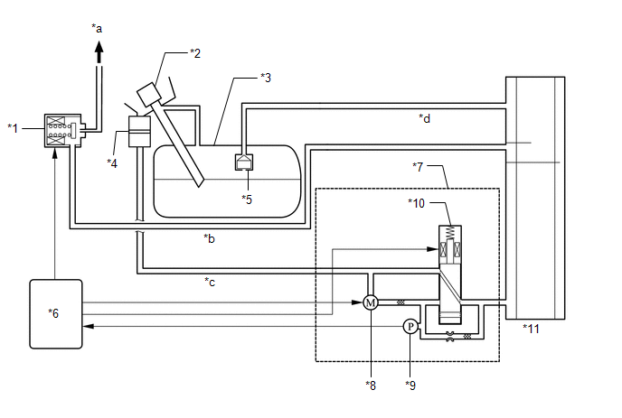
SYSTEM DIAGRAM
|
*1 | Purge Valve (Purge VSV) |
*2 | Fuel Tank Cap Assembly |
|
*3 | Fuel Tank Assembly |
*4 | Canister Filter |
|
*5 | Fuel Cut-off Valve |
*6 | ECM |
|
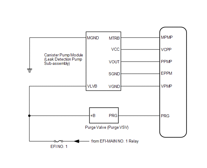
*7 | Canister Pump Module (Charcoal Canister Leak Detection Pump Sub-assembly) |
*8 | Pump Motor |
|
*9 | Canister Pressure Sensor |
*10 | Vent Valve |
|
*11 | Canister (Charcoal Canister Assembly) |
- | - |
|
*a | to Intake Manifold |
*b | Purge Line |
|
*c | Air Line |
*d | Vent Line |
READ NEXT:
 On-vehicle Inspection
ON-VEHICLE INSPECTION PROCEDURE
1. INSPECT FUEL CUT OPERATION (a) Start the engine. (b) Warm up the engine.
(c) Increase the engine speed to approximately 3500 rpm. (d) Use a sound scope to check
Fuel Tank Cap
InspectionINSPECTION PROCEDURE
1. INSPECT FUEL TANK CAP ASSEMBLY
(a) Visually check that the fuel tank cap assembly and gasket are not deformed or damaged.
If the result is not as specified
Pcv Valve
ComponentsCOMPONENTS ILLUSTRATION
*1 PCV VALVE (VENTILATION VALVE SUB-ASSEMBLY)
*2 V-BANK COVER SUB-ASSEMBLY
*3 VENTILATION HOSE
- -
N*m (kgf*cm, f
SEE MORE:
Hydraulic Test
HYDRAULIC TEST PERFORM HYDRAULIC TEST
CAUTION:
Do not perform a stall test if there are any people or objects near the vehicle.
The vehicle could begin moving suddenly, resulting in a serious accident.
Do not perform a stall test if any wheel chocks are out of position.
Sound Signal Circuit between Radio Receiver and Stereo Component Amplifier
DESCRIPTION The radio and display receiver assembly sends a sound signal to the stereo component amplifier assembly via this circuit.
The sound signal that is sent is amplified by the stereo component amplifier assembly, and then is sent to the speakers.
If there is an open or short in this circ
© 2023-2025 Copyright www.tocamry.com
