Toyota Camry (XV70): Parts Location
Toyota Camry Repair Manual XV70 (2018-2024) / Engine, Hybrid System / 2gr-fks (fuel) / Fuel System / Parts Location
PARTS LOCATION
ILLUSTRATION
|
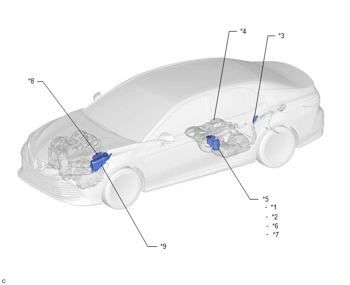
*1 | FUEL SENDER GAUGE ASSEMBLY |
*2 | FUEL PUMP (for Low Pressure) |
|
*3 | FUEL PUMP CONTROL ECU |
*4 | FUEL TANK ASSEMBLY |
|
*5 | FUEL SUCTION TUBE WITH PUMP AND GAUGE ASSEMBLY |
*6 | FUEL MAIN VALVE ASSEMBLY (for Low Pressure) |
|
*7 | FUEL MAIN VALVE ASSEMBLY (for High Pressure) |
*8 | ECM |
|
*9 | ENGINE ROOM RELAY BLOCK AND JUNCTION BLOCK ASSEMBLY - EFI MAIN NO. 2 RELAY - EFI MAIN NO. 2 FUSE - INJ FUSE |
- | - |
ILLUSTRATION
|
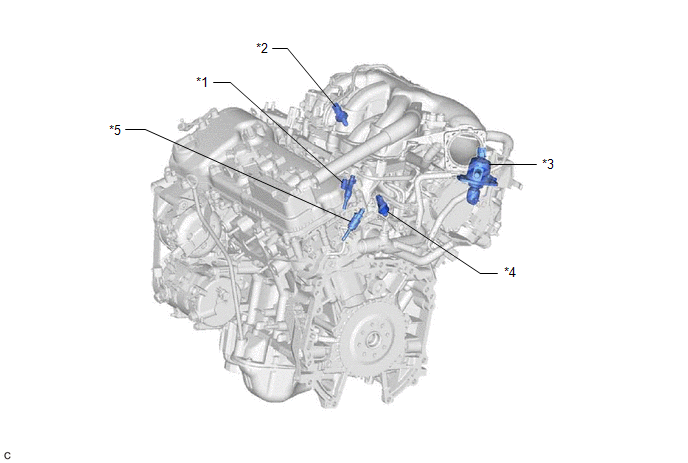
*1 | FUEL INJECTOR ASSEMBLY (for Port Injection) |
*2 | FUEL PRESSURE SENSOR (FUEL DELIVERY PIPE WITH SENSOR ASSEMBLY) (for Low Pressure) |
|
*3 | FUEL PUMP ASSEMBLY (for High Pressure) |
*4 | FUEL PRESSURE SENSOR (FUEL DELIVERY PIPE WITH SENSOR ASSEMBLY LH) (for High Pressure) |
|
*5 | FUEL INJECTOR ASSEMBLY (for Direct Injection) |
- | - |
READ NEXT:
 System Diagram
SYSTEM DIAGRAM FUEL FLOW DIAGRAM
*A for Direct Injection
- -
*1 Fuel Injector Assembly
*2 Throttle Body with Motor Assembly
*3 Fuel Pressure Sensor (Fue
SEE MORE:
Steering wheel
Adjustment procedure
1. Hold the steering wheel and
push the lever down.
2. Adjust to the ideal position by
moving the steering wheel horizontally
and vertically.
After adjustment, pull the lever up
to secure the steering wheel.
Horn
To sound the horn, press on or
close to the mark.
Removal
REMOVAL CAUTION / NOTICE / HINT
The necessary procedures (adjustment, calibration, initialization or registration) that must be performed after parts are removed and installed, or replaced during vacuum warning switch assembly removal/installation are shown below. Necessary Procedures After Parts
© 2023-2025 Copyright www.tocamry.com
