Toyota Camry (XV70): Removal
REMOVAL
CAUTION / NOTICE / HINT
The necessary procedures (adjustment, calibration, initialization or registration) that must be performed after parts are removed and installed, or replaced during vacuum warning switch assembly removal/installation are shown below.
Necessary Procedures After Parts Removed/Installed/Replaced|
Replaced Part or Performed Procedure |
Necessary Procedure | Effect/Inoperative Function when Necessary Procedure not Performed |
Link |
|---|---|---|---|
|
Disconnect cable from negative battery terminal |
Perform steering sensor zero point calibration |
Lane tracing assist system |
|
|
Pre-collision system | |||
|
Memorize steering angle neutral point |
Parking assist monitor system |
| |
|
Panoramic view monitor system |
|
PROCEDURE
1. PRECAUTION
NOTICE:
After turning the ignition switch off, waiting time may be required before disconnecting the cable from the negative (-) battery terminal. Therefore, make sure to read the disconnecting the cable from the negative (-) battery terminal notices before proceeding with work.
Click here .gif)
2. REMOVE BATTERY
for A25A-FKS: Click here
for 2GR-FKS: Click here
3. REMOVE VACUUM WARNING SWITCH ASSEMBLY
| (a) Disconnect the connector from the vacuum warning switch assembly. |
|
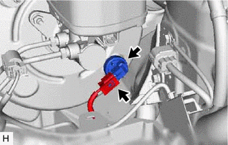
(b) Remove the vacuum warning switch assembly from the brake booster assembly.
4. REMOVE CHECK VALVE GROMMET
(a) Remove the check valve grommet from the brake booster assembly.
READ NEXT:
 Installation
INSTALLATION PROCEDURE 1. INSTALL CHECK VALVE GROMMET
(a) Install a new check valve grommet to the brake booster assembly. 2. INSTALL VACUUM WARNING SWITCH ASSEMBLY
(a) Install the vacuum warning
SEE MORE:
On-vehicle Inspection
ON-VEHICLE INSPECTION CAUTION / NOTICE / HINT
HINT: Refer to Problem Symptoms Table. Click here
PROCEDURE
1. REMOVE FRONT WHEEL OPENING EXTENSION PAD LH Click here
2. REMOVE FRONT WHEEL OPENING EXTENSION PAD RH
Click here
3. REMOVE NO. 1 ENGINE UNDER COVER Click he
Removal
REMOVAL CAUTION / NOTICE / HINT
The necessary procedures (adjustment, calibration, initialization, or registration) that must be performed after parts are removed and installed, or replaced during clearance warning ECU assembly removal/installation are shown below. Necessary Procedure After Parts
