Toyota Camry (XV70): Rear Brake Pad Replacement Mode
REAR BRAKE PAD REPLACEMENT MODE
REAR BRAKE PAD REPLACEMENT MODE
|
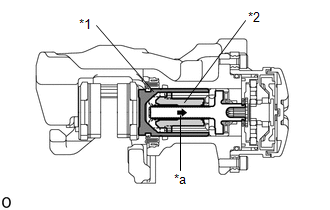
*1 | Rear Disc Brake Piston |
|
*2 | Nut |
|
*a | The nut moves inward in pad replacement mode |
HINT:
When replacing the rear disc brake pad and rear disc, since the nut inside the rear disc brake cylinder assembly is in an advanced position, it is necessary to move the nut back inside the cylinder. The nut can be moved back using pad replacement mode.
(a) Pad replacement mode
When Using the Techstream:- Select "EPB Full Release" using the Techstream.
NOTICE:
The parking brake must be released.
- Follow the Techstream display and select "Next".
NOTICE:
- Make sure to perform this procedure with the ignition switch to ON.
- Make sure that the brake pedal is not depressed when performing this procedure.
- When the system changes to pad replacement mode, DTC C060E2A, C06132A or C13B800 may be stored. If the DTC is stored, clear the DTCs after the procedure (rear brake pad replacement, etc.) is complete.
HINT:
Once the operation finishes, the parking brake indicator light flashes slowly (1 second intervals) (nut moves back inside the cylinder and system enters pad replacement mode).
|
Tester Display |
|---|
| EPB Full Release |
- Turn the ignition switch off.
- Turn the ignition switch to ON.
- Within 8 seconds, operate the electric parking brake switch to the lock side 3 times (switch off to on (lock side) 3 times) and then operate the electric parking brake switch to the release side 3 times (switch off to on (release side) 3 times).
NOTICE:
- If the operation is performed too quickly, the system may not respond. If the system does not respond, perform the operation again at a slower speed.
- The parking brake must be released.
HINT:
The parking brake indicator light flashes (0.25 second intervals).
- Hold the electric parking brake switch at the release side for 5 seconds or more.
NOTICE:
- Make sure to perform this procedure with the ignition switch to ON.
- Make sure that the brake pedal is not depressed when performing this procedure.
- When the system changes to pad replacement mode, DTC C060E2A, C06132A or C13B800 may be stored. If the DTC is stored, clear the DTCs after the procedure (rear brake pad replacement, etc.) is complete.
HINT:
After a short time passes, the parking brake actuator assembly operates, and once the assembly finishes operating, the parking brake indicator light flashes slowly (1 second intervals) (nut moves back inside the cylinder and system enters pad replacement mode).
(b) Turn the ignition switch off.
NOTICE:
Do not operate the electric parking brake switch (integration control and panel assembly) until the procedure is complete. If operated, the system will return to its normal condition.
When Using the Techstream:- Disconnect the Techstream from the DLC3.
(c) Normal condition recovery
(1) After the procedure (rear brake pad replacement, etc.) is complete, turn the ignition switch to ON and hold the electric parking brake switch at the lock side for 5 seconds or more.
NOTICE:
- When performing work (replacing the rear brake pad, etc.), do not operate the electric parking brake switch (integration control and panel assembly) or turn the ignition switch to ON and operate the shift lever. If the electric parking brake switch (integration control and panel assembly) or shift lever is operated, the parking brake may operate and the rear disc brake piston may fall off. Also, make sure to disconnect the connector of the parking brake actuator assembly or disconnect the cable from the negative (-) auxiliary battery terminal.
- When DTC C060E2A, C06132A or C13B800 is stored, clear the DTCs.
READ NEXT:
 Brake System Control Module "A" System Internal Failure (C059704,C059746,C060B49,C061049,C13CF1C,C13D41C)
DESCRIPTION The following DTCs are stored when a malfunction occurs in the skid control ECU (brake actuator assembly).
DTC No. Detection Item
DTC Detection Condition Trouble Area
M
Electric Parking Brake Switch Signal Compare Failure (C060962)
DESCRIPTION When the electric parking brake switch is pulled, a lock request signal is sent from the skid control ECU (brake actuator assembly) to the parking brake actuator assembly. When the electri
Left Electric Parking Brake Actuator Control (C060B00,C060B11)
DESCRIPTION
DTC No. Detection Item
DTC Detection Condition Trouble Area
Memory Note
C060B00 Left Electric Parking Brake Actuator Control
Diagnosis Condition:
SEE MORE:
Wireless charger (if equipped)
A portable device, such as a smartphone or mobile battery, can be
charged by just placing it on the charging area, provided the device is
compatible with the Qi wireless charging standard created by the
Wireless Power Consortium.
The wireless charger cannot be used with a portable device that
Removal
REMOVAL CAUTION / NOTICE / HINT
The necessary procedures (adjustment, calibration, initialization, or registration) that must be performed after parts are removed and installed, or replaced during front crankshaft oil seal removal/installation are shown below. Necessary Procedure After Parts Remov
