Toyota Camry (XV70): Reassembly
REASSEMBLY
CAUTION / NOTICE / HINT
NOTICE:
- When using a vise, place aluminum plates between the part and vise.
- When using a vise, do not overtighten it.
HINT:
- Use the same procedure for the RH and LH sides.
- The procedure listed below is for the LH side.
PROCEDURE
1. INSTALL OUTBOARD JOINT BOOT
(a) Wrap the splines of the rear drive outboard joint shaft assembly LH with protective tape to prevent the boot from being damaged.
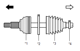
(b) Install new parts to the rear drive outboard joint shaft assembly LH in the following order:
|
*1 | Rear Drive Outboard Joint Shaft Assembly LH |
|
*2 | Rear No. 2 Drive Shaft Outboard Joint Boot Clamp LH |
|
*3 | Outboard Joint Boot |
|
*4 | Rear Drive Shaft Outboard Joint Boot Clamp LH |
.png) |
Outboard Joint Side |
.png) |
Inboard Joint Side |
(1) Rear No. 2 drive shaft outboard joint boot clamp LH
(2) Outboard joint boot
(3) Rear drive shaft outboard joint boot clamp LH
(c) Pack the joint portion of the rear drive outboard joint shaft assembly LH and outboard joint boot with grease.
Standard Grease Capacity:
37 to 47 g (1.31 to 1.65 oz.)
(d) Install the outboard joint boot to the rear drive outboard joint shaft assembly LH groove.
NOTICE:
- Do not allow grease to adhere to the boot clamp track of the outboard joint boot.
- Keep the inside of the outboard joint boot free of foreign matter.
2. INSTALL REAR NO. 2 DRIVE SHAFT OUTBOARD JOINT BOOT CLAMP LH
CAUTION:
- When installing the rear No. 2 drive shaft outboard joint boot clamp LH, do not perform the work without wearing protective gloves.
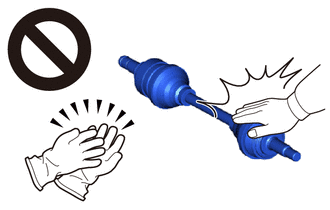
- If work is performed without using protective gloves, injuries may occur.
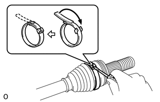
| (a) Using a screwdriver, install the rear No. 2 drive shaft outboard joint boot clamp LH as shown in the illustration. NOTICE: Be careful not to damage the outboard joint boot. |
|
3. INSTALL REAR DRIVE SHAFT OUTBOARD JOINT BOOT CLAMP LH
(a) Install the rear drive shaft outboard joint boot clamp LH onto the outboard joint boot.
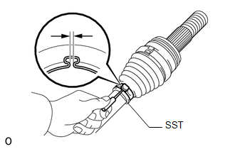
| (b) Place SST onto the rear drive shaft outboard joint boot clamp LH. SST: 09521-24010 |
|
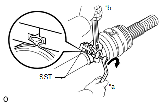
(c) Tighten SST so that the rear drive shaft outboard joint boot clamp LH is pinched.
NOTICE:
- Do not overtighten SST.
- Be careful not to damage the outboard joint boot.
| (d) Using SST, measure the clearance of the rear drive shaft outboard joint boot clamp LH. SST: 09240-00021 Standard Clearance: 1.2 mm (0.0472 in.) or less NOTICE: If the measured value exceeds the specified value, retighten the rear drive shaft outboard joint boot clamp LH. |
|
4. INSTALL REAR DRIVE SHAFT INBOARD JOINT ASSEMBLY LH
(a) Wrap the spline of the rear drive outboard joint shaft assembly LH with protective tape to prevent the boot from being damaged.
|
*1 | Rear Drive Shaft Inboard Joint Boot Clamp LH |
|
*2 | Inboard Joint Boot |
|
*3 | Rear No. 2 Drive Shaft Inboard Joint Boot Clamp LH |
|
*a | Protective Tape |
|
|
Outboard Joint Side |
|
|
Inboard Joint Side |
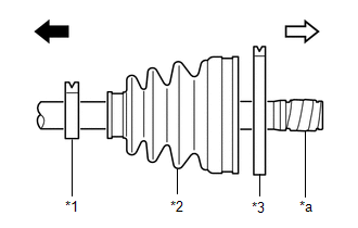
(b) Install new parts to the rear drive outboard joint shaft assembly LH in the following order.
(1) Rear drive shaft inboard joint boot clamp LH
(2) Inboard joint boot
(3) Rear No. 2 drive shaft inboard joint boot clamp LH
(c) Remove the protective tape from the rear drive outboard joint shaft assembly LH.
| (d) Align the matchmarks and place the beveled side of the tripod joint axial spline toward the rear drive outboard joint shaft assembly LH. NOTICE: Face the serrated side of the tripod joint outward and install it to the outboard joint end. |
|
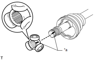
(e) Using a brass bar and hammer, tap the tripod joint onto the rear drive outboard joint shaft assembly LH.
NOTICE:
- Do not tap the rollers.
- Be sure to install the tripod joint in the correct direction.
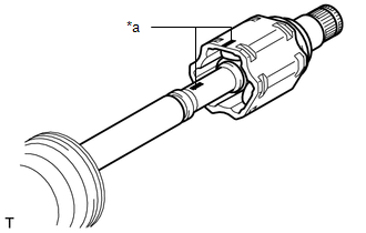
| (f) Using a snap ring expander, install a new rear drive shaft snap ring LH. |
|
.png)
(g) Pack the rear drive shaft inboard joint assembly LH and inboard joint boot with grease from the boot kit.
Standard Grease Capacity:
88 to 98 g (3.11 to 3.45 oz.)
| (h) Align the matchmarks and install the rear drive shaft inboard joint assembly LH to the rear drive outboard joint shaft assembly LH. |
|
5. INSTALL INBOARD JOINT BOOT
(a) Install the inboard joint boot to the rear drive shaft inboard joint assembly LH.
| (b) Check whether the drive shaft dimension (A) is within specification. Length (A): 749.1 to 759.1 mm (2.46 to 2.49 ft.) NOTICE: Keep the drive shaft assembly level during inspection. If the boots are stretched or contracted, correct them. |
|
.png)
6. INSTALL REAR NO. 2 DRIVE SHAFT INBOARD JOINT BOOT CLAMP LH
(a) for Type A:
| (1) Using needle-nose pliers, install the rear No. 2 drive shaft inboard joint boot clamp LH as shown in the illustration. NOTICE: Be careful not to damage the inboard joint boot. |
|
.png)
(b) for Type B:
| (1) Using needle-nose pliers, install the rear No. 2 drive shaft inboard joint boot clamp LH as shown in the illustration. NOTICE: Be careful not to damage the inboard joint boot. |
|
.png)
7. INSTALL REAR DRIVE SHAFT INBOARD JOINT BOOT CLAMP LH
HINT:
Use the same procedure described for the rear No. 2 drive shaft inboard joint boot clamp LH.
8. INSPECT REAR DRIVE SHAFT
Click here
.gif)
READ NEXT:
 Installation
INSTALLATION CAUTION / NOTICE / HINT
HINT:
Use the same procedure for the RH and LH sides.
The procedure listed below is for the LH side.
PROCEDURE 1. INSTALL REAR DRIVE SHAFT INBOARD JO
4wd Control Ecu
ComponentsCOMPONENTS ILLUSTRATION
*1 NO. 3 INSTRUMENT PANEL TO COWL BRACE SUB-ASSEMBLY
*2 4WD ECU ASSEMBLY
N*m (kgf*cm, ft.*lbf): Specified torque
- - Rem
SEE MORE:
Active Control Engine Mount System
DESCRIPTION LOCATION
*1 Vacuum Switching Valve (for Active Control Engine Mount System)
*2 Front Engine Mounting Insulator
*3 Rear Engine Mounting Insulator
- -
The active control engine mount system decreases engine vibration at a low engine speed using th
Front Side Marker Light Bulb
ComponentsCOMPONENTS ILLUSTRATION
*1 FRONT SIDE MARKER LIGHT BULB
- - RemovalREMOVAL CAUTION / NOTICE / HINT
HINT:
Use the same procedure for the RH side and LH side.
The following procedure is for the LH side.
PROCEDURE 1. REMOVE FRONT SIDE MARKER LIGHT BULB
(
