Toyota Camry (XV70): Removal
REMOVAL
PROCEDURE
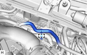
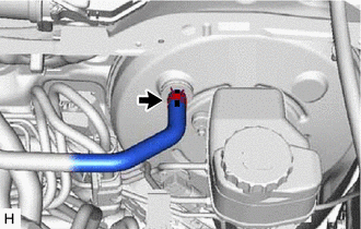
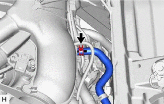
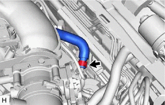
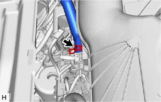
1. REMOVE UNION TO CHECK VALVE HOSE (for A25A-FKS)
| (a) Slide the clip and disconnect the union to check valve hose from the brake booster assembly. |
|
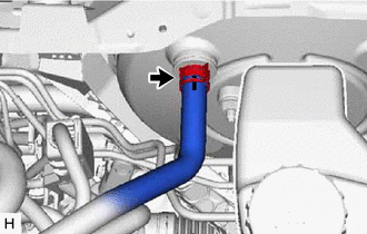
| (b) Slide the clip and disconnect the union to check valve hose from the No. 1 vacuum hose connector. |
|
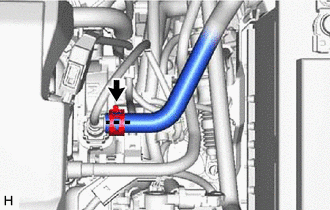
(c) Remove the 2 clips from the union to check valve hose.
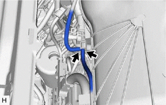
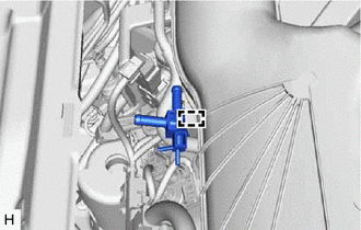
2. REMOVE NO. 1 VACUUM HOSE CONNECTOR (for A25A-FKS)
| (a) Disconnect the vacuum hose from the No. 1 vacuum hose connector. |
|
(b) Pinch the retainer of the No. 1 vacuum hose connector, and then pull the No. 1 vacuum hose connector off of the vacuum pump assembly.
NOTICE:
Be sure to remove the No. 1 vacuum hose connector by hand.
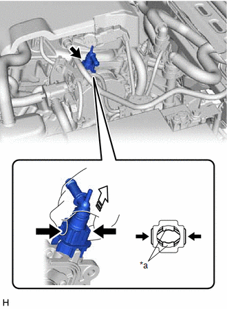
|
*a | Retainer |
.png) |
Pinch |
.png) |
Pull off |
3. REMOVE COWL TOP VENTILATOR LOUVER SUB-ASSEMBLY (for 2GR-FKS)
Click here .gif)
4. REMOVE FRONT CENTER UPPER SUSPENSION BRACE SUB-ASSEMBLY (for 2GR-FKS)
Click here
5. REMOVE UNION TO CHECK VALVE HOSE (for 2GR-FKS)
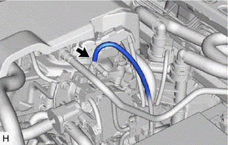
| (a) Disengage the clamp to separate the union to check valve hose from the air tube. |
|
| (b) Slide the clip and disconnect the union to check valve hose from the brake booster assembly. |
|
| (c) Slide the clip and disconnect the union to check valve hose from the air delivery way. |
|
(d) Remove the 2 clips from the union to check valve hose.
6. REMOVE AIR TUBE (for 2GR-FKS)
| (a) Disconnect the 2 vacuum transmitting hose assemblies from the air delivery way. |
|
| (b) Slide the clip and disconnect the air tube from the vacuum pump assembly. |
|
| (c) Slide the clip and disconnect the air tube from the air delivery way. |
|
(d) Remove the 2 clips from the air tube.
| (e) Disengage the clamp to remove the air delivery way from the intake air surge tank assembly. |
|
READ NEXT:
 Installation
INSTALLATION PROCEDURE 1. INSTALL NO. 1 VACUUM HOSE CONNECTOR (for A25A-FKS)
(a) Align the No. 1 vacuum hose connector with the vacuum pump assembly, and push them together until the No. 1 vacuum ho
Differential Oil
ComponentsCOMPONENTS ILLUSTRATION
*1 REAR DIFFERENTIAL FILLER PLUG
*2 REAR DIFFERENTIAL DRAIN PLUG
*3 GASKET
- -
N*m (kgf*cm, ft.*lbf): Specified t
SEE MORE:
Steering Angle Sensor Module Circuit Voltage Out of Range (C05261C)
DESCRIPTION The skid control ECU (brake actuator assembly) compares the calculated steering angle value based on the yaw rate sensor value with the actual steering angle value of the steering sensor.
DTC No. Detection Item
DTC Detection Condition Trouble Area
C05261C Steerin
Speaker Output Short (B15C3)
DESCRIPTION This DTC is stored when a malfunction occurs in the speakers.
DTC No. Detection Item
DTC Detection Condition Trouble Area
B15C3 Speaker Output Short
A short is detected in the speaker output circuit
Harness or connector
Speaker
Radio
