Toyota Camry (XV70): Speaker Output Short (B15C3)
DESCRIPTION
This DTC is stored when a malfunction occurs in the speakers.
|
DTC No. | Detection Item |
DTC Detection Condition | Trouble Area |
|---|---|---|---|
|
B15C3 | Speaker Output Short |
A short is detected in the speaker output circuit |
|
- *1: for 6 Speakers
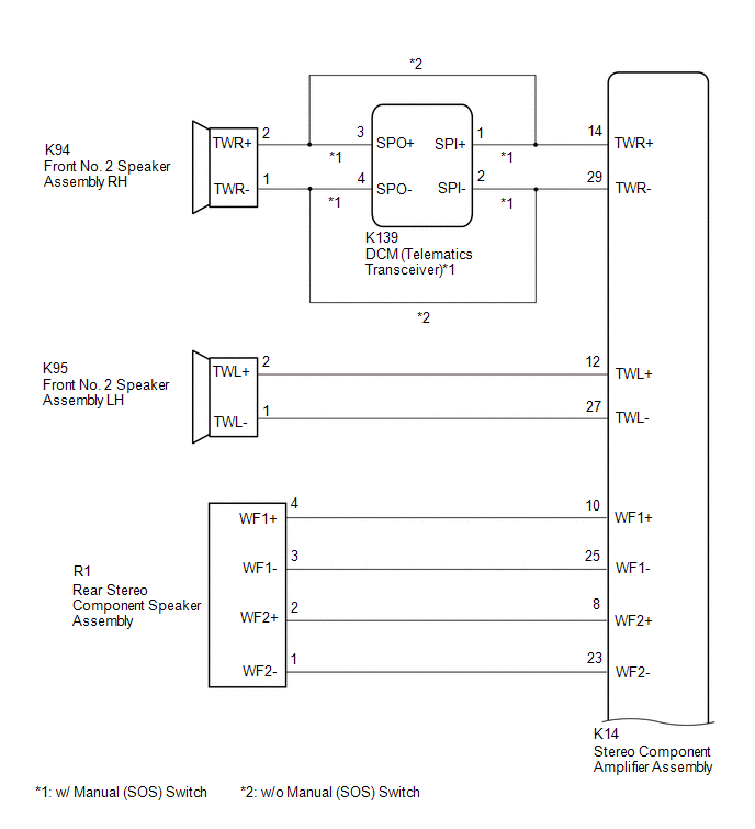
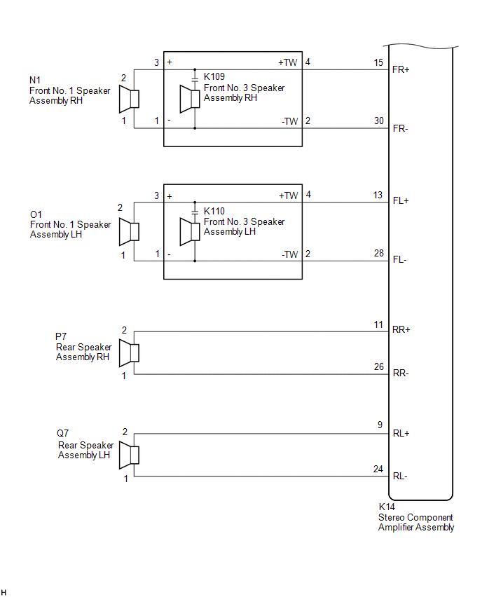
*2: for 9 Speakers
*3: w/ Manual (SOS) Switch
WIRING DIAGRAM
for 6 Speakers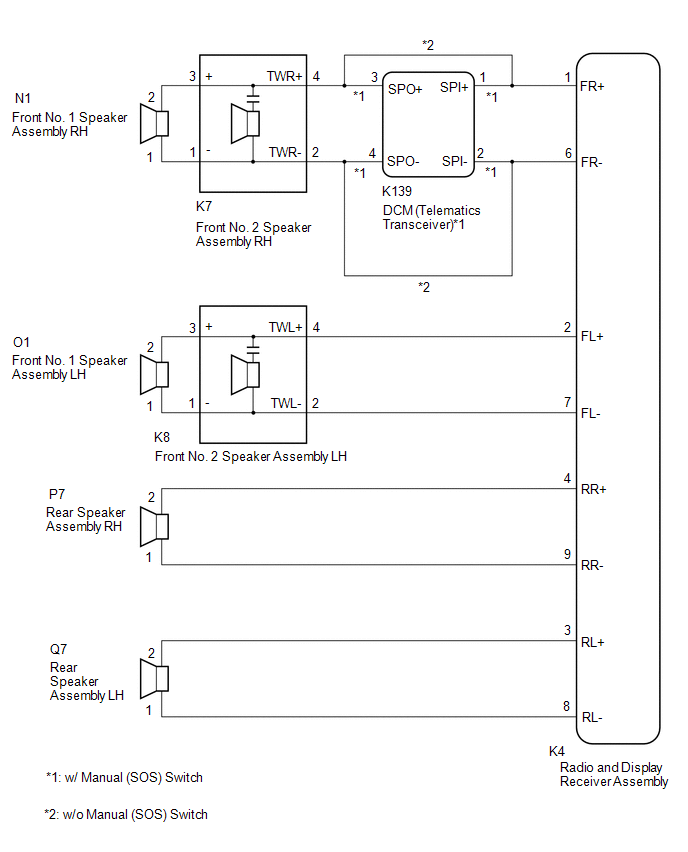 for 9 Speakers
CAUTION / NOTICE / HINT
NOTICE:
- Depending on the parts that are replaced during vehicle inspection or maintenance, performing initialization, registration or calibration may be needed. Refer to Precaution for Audio and Visual System.
Click here
.gif)
- When replacing the radio and display receiver assembly, always replace it with a new one. If a radio and display receiver assembly which was installed to another vehicle is used, the following may occur:
- A communication malfunction DTC may be stored.
- The radio and display receiver assembly may not operate normally.
- Before replacing the DCM (telematics transceiver), refer to Registration.
Click here
PROCEDURE
|
1. | CHECK MODEL |
(a) Choose the model to be inspected.
|
Result | Proceed to |
|---|---|
|
for 6 Speakers (w/ Manual (SOS) Switch) |
A |
| for 6 Speakers (w/o Manual (SOS) Switch) |
B |
| for 9 Speakers (w/ Manual (SOS) Switch) |
C |
| for 9 Speakers (w/o Manual (SOS) Switch) |
D |
| B |
.gif) | GO TO STEP 5 |
| C |
| GO TO STEP 10 |
| D |
| GO TO STEP 13 |
|
.gif)
| 2. |
CHECK HARNESS AND CONNECTOR (RADIO AND DISPLAY RECEIVER ASSEMBLY, DCM (TELEMATICS TRANSCEIVER) OR SPEAKERS - BODY GROUND) |
(a) Disconnect the K4 radio and display receiver assembly connector.
(b) Disconnect the K139 DCM (telematics transceiver) connector.
(c) Disconnect the K7 and K8 front No. 2 speaker assembly connectors.
(d) Disconnect the Q7 and P7 rear speaker assembly connectors.
(e) Measure the resistance according to the value(s) in the table below.
Standard Resistance:
|
Tester Connection | Condition |
Specified Condition |
|---|---|---|
|
K4-1 (FR+) or K139-1 (SPI+) - Body ground |
Always | 10 kΩ or higher |
|
K4-6 (FR-) or K139-2 (SPI-) - Body ground |
Always | 10 kΩ or higher |
|
K4-2 (FL+) or K8-4 (TWL+) - Body ground |
Always | 10 kΩ or higher |
|
K4-7 (FL-) or K8-2 (TWL-) - Body ground |
Always | 10 kΩ or higher |
|
K4-4 (RR+) or P7-2 - Body ground |
Always | 10 kΩ or higher |
|
K4-9 (RR-) or P7-1 - Body ground |
Always | 10 kΩ or higher |
|
K4-3 (RL+) or Q7-2 - Body ground |
Always | 10 kΩ or higher |
|
K4-8 (RL-) or Q7-1 - Body ground |
Always | 10 kΩ or higher |
| NG | | REPAIR OR REPLACE HARNESS OR CONNECTOR |
|
| 3. |
CHECK HARNESS AND CONNECTOR (DCM (TELEMATICS TRANSCEIVER) OR SPEAKER - BODY GROUND) |
(a) Disconnect the K139 DCM (telematics transceiver) connector.
(b) Disconnect the K7 front No. 2 speaker assembly RH connector.
(c) Measure the resistance according to the value(s) in the table below.
Standard Resistance:
|
Tester Connection | Condition |
Specified Condition |
|---|---|---|
|
K139-3 (SPO+) or K7-4 (TWR+) - Body ground |
Always | 10 kΩ or higher |
|
K139-4 (SPO-) or K7-2 (TWR-) - Body ground |
Always | 10 kΩ or higher |
| NG | | REPAIR OR REPLACE HARNESS OR CONNECTOR |
|
| 4. |
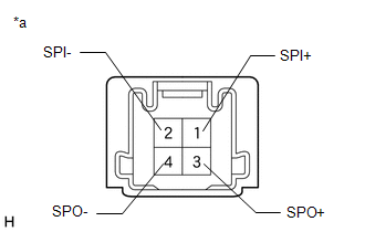
INSPECT DCM (TELEMATICS TRANSCEIVER) |
(a) Remove the DCM (telematics transceiver).
Click here
| (b) Measure the resistance according to the value(s) in the table below. Standard Resistance:
|
|
| OK | | GO TO STEP 6 |
| NG | | REPLACE DCM (TELEMATICS TRANSCEIVER)
|
| 5. |
CHECK HARNESS AND CONNECTOR (RADIO AND DISPLAY RECEIVER ASSEMBLY OR SPEAKERS - BODY GROUND) |
(a) Disconnect the K4 radio and display receiver assembly connector.
(b) Disconnect the K7 and K8 front No. 2 speaker assembly connectors.
(c) Disconnect the Q7 and P7 rear speaker assembly connectors.
(d) Measure the resistance according to the value(s) in the table below.
Standard Resistance:
|
Tester Connection | Condition |
Specified Condition |
|---|---|---|
|
K4-1 (FR+) or K7-4 (TWR+) - Body ground |
Always | 10 kΩ or higher |
|
K4-6 (FR-) or K7-2 (TWR-) - Body ground |
Always | 10 kΩ or higher |
|
K4-2 (FL+) or K8-4 (TWL+) - Body ground |
Always | 10 kΩ or higher |
|
K4-7 (FL-) or K8-2 (TWL-) - Body ground |
Always | 10 kΩ or higher |
|
K4-4 (RR+) or P7-2 - Body ground |
Always | 10 kΩ or higher |
|
K4-9 (RR-) or P7-1 - Body ground |
Always | 10 kΩ or higher |
|
K4-3 (RL+) or Q7-2 - Body ground |
Always | 10 kΩ or higher |
|
K4-8 (RL-) or Q7-1 - Body ground |
Always | 10 kΩ or higher |
| NG | | REPAIR OR REPLACE HARNESS OR CONNECTOR |
|
| 6. |
CHECK HARNESS AND CONNECTOR (FRONT NO. 1 SPEAKER ASSEMBLY OR FRONT NO. 2 SPEAKER ASSEMBLY - BODY GROUND) |
(a) Disconnect the N1 and O1 front No. 1 speaker assembly connectors.
(b) Disconnect the K7 and K8 front No. 2 speaker assembly connectors.
(c) Measure the resistance according to the value(s) in the table below.
Standard Resistance:
|
Tester Connection | Condition |
Specified Condition |
|---|---|---|
|
N1-2 or K7-3 (+) - Body ground |
Always | 10 kΩ or higher |
|
N1-1 or K7-1 (-) - Body ground |
Always | 10 kΩ or higher |
|
O1-2 or K8-3 (+) - Body ground |
Always | 10 kΩ or higher |
|
O1-1 or K8-1 (-) - Body ground |
Always | 10 kΩ or higher |
| NG | | REPAIR OR REPLACE HARNESS OR CONNECTOR |
|
| 7. |
INSPECT FRONT NO. 1 SPEAKER ASSEMBLY |
(a) Remove the front No. 1 speaker assembly.
Click here
(b) Inspect the front No. 1 speaker assembly.
Click here
| NG | | REPLACE FRONT NO. 1 SPEAKER ASSEMBLY |
|
| 8. |
INSPECT REAR SPEAKER ASSEMBLY |
(a) Remove the rear speaker assembly.
Click here
(b) Inspect the rear speaker assembly.
Click here
| NG | | REPLACE REAR SPEAKER ASSEMBLY |
|
| 9. |
REPLACE FRONT NO. 2 SPEAKER ASSEMBLY |
(a) Remove the front No. 2 speaker assembly.
Click here
(b) Inspect the front No. 2 speaker assembly.
Click here
(c) Clear the DTCs.
Body Electrical > Navigation System > Clear DTCs(d) Recheck for DTCs and check that no DTCs are output.
Body Electrical > Navigation System > Trouble CodesOK:
No DTCs are output.
| OK | |
END |
| NG | | REPLACE RADIO AND DISPLAY RECEIVER ASSEMBLY
|
| 10. |
CHECK HARNESS AND CONNECTOR (STEREO COMPONENT AMPLIFIER ASSEMBLY, DCM (TELEMATICS TRANSCEIVER) OR SPEAKERS - BODY GROUND) |
(a) Disconnect the K14 stereo component amplifier assembly connector.
(b) Disconnect the K139 DCM (telematics transceiver) connector.
(c) Disconnect the K95 front No. 2 speaker assembly LH connector.
(d) Disconnect the K109 and K110 front No. 3 speaker assembly connectors.
(e) Disconnect the P7 and Q7 rear speaker assembly connectors.
(f) Disconnect the R1 rear stereo component speaker assembly connector.
(g) Measure the resistance according to the value(s) in the table below.
Standard Resistance:
|
Tester Connection | Condition |
Specified Condition |
|---|---|---|
|
K14-14 (TWR+) or K139-1 (SPI+) - Body ground |
Always | 10 kΩ or higher |
|
K14-29 (TWR-) or K139-2 (SPI-) - Body ground |
Always | 10 kΩ or higher |
|
K14-12 (TWL+) or K95-2 (TWL+) - Body ground |
Always | 10 kΩ or higher |
|
K14-27 (TWL-) or K95-1 (TWL-) - Body ground |
Always | 10 kΩ or higher |
|
K14-15 (FR+) or K109-4 (+TW) - Body ground |
Always | 10 kΩ or higher |
|
K14-30 (FR-) or K109-2 (-TW) - Body ground |
Always | 10 kΩ or higher |
|
K14-13 (FL+) or K110-4 (+TW) - Body ground |
Always | 10 kΩ or higher |
|
K14-28 (FL-) or K110-2 (-TW) - Body ground |
Always | 10 kΩ or higher |
|
K14-11 (RR+) or P7-2 - Body ground |
Always | 10 kΩ or higher |
|
K14-26 (RR-) or P7-1 - Body ground |
Always | 10 kΩ or higher |
|
K14-9 (RL+) or Q7-2 - Body ground |
Always | 10 kΩ or higher |
|
K14-24 (RL-) or Q7-1 - Body ground |
Always | 10 kΩ or higher |
|
K14-10 (WF1+) or R1-4 (WF1+) - Body ground |
Always | 10 kΩ or higher |
|
K14-25 (WF1-) or R1-3 (WF1-) - Body ground |
Always | 10 kΩ or higher |
|
K14-8 (WF2+) or R1-2 (WF2+) - Body ground |
Always | 10 kΩ or higher |
|
K14-23 (WF2-) or R1-1 (WF2-) - Body ground |
Always | 10 kΩ or higher |
| NG | | REPAIR OR REPLACE HARNESS OR CONNECTOR |
|
| 11. |
CHECK HARNESS AND CONNECTOR (DCM (TELEMATICS TRANSCEIVER) OR SPEAKER - BODY GROUND) |
(a) Disconnect the K139 DCM (telematics transceiver) connector.
(b) Disconnect the K94 front No. 2 speaker assembly RH connector.
(c) Measure the resistance according to the value(s) in the table below.
Standard Resistance:
|
Tester Connection | Condition |
Specified Condition |
|---|---|---|
|
K139-3 (SPO+) or K94-2 (TWR+) - Body ground |
Always | 10 kΩ or higher |
|
K139-4 (SPO-) or K94-1 (TWR-) - Body ground |
Always | 10 kΩ or higher |
| NG | | REPAIR OR REPLACE HARNESS OR CONNECTOR |
|
| 12. |
INSPECT DCM (TELEMATICS TRANSCEIVER) |
(a) Remove the DCM (telematics transceiver).
Click here
| (b) Measure the resistance according to the value(s) in the table below. Standard Resistance:
|
|
| OK | | GO TO STEP 14 |
| NG | | REPLACE DCM (TELEMATICS TRANSCEIVER)
|
| 13. |
CHECK HARNESS AND CONNECTOR (STEREO COMPONENT AMPLIFIER ASSEMBLY OR SPEAKERS - BODY GROUND) |
(a) Disconnect the K14 stereo component amplifier assembly connector.
(b) Disconnect the K109 and K110 front No. 3 speaker assembly connectors.
(c) Disconnect the K94 and K95 front No. 2 speaker assembly connectors.
(d) Disconnect the P7 and Q7 rear speaker assembly connectors.
(e) Disconnect the R1 rear stereo component speaker assembly connector.
(f) Measure the resistance according to the value(s) in the table below.
Standard Resistance:
|
Tester Connection | Condition |
Specified Condition |
|---|---|---|
|
K14-15 (FR+) or K109-4 (+TW) - Body ground |
Always | 10 kΩ or higher |
|
K14-30 (FR-) or K109-2 (-TW) - Body ground |
Always | 10 kΩ or higher |
|
K14-13 (FL+) or K110-4 (+TW) - Body ground |
Always | 10 kΩ or higher |
|
K14-28 (FL-) or K110-2 (-TW) - Body ground |
Always | 10 kΩ or higher |
|
K14-14 (TWR+) or K94-2 (TWR+) - Body ground |
Always | 10 kΩ or higher |
|
K14-29 (TWR-) or K94-1 (TWR-) - Body ground |
Always | 10 kΩ or higher |
|
K14-12 (TWL+) or K95-2 (TWL+) - Body ground |
Always | 10 kΩ or higher |
|
K14-27 (TWL-) or K95-1 (TWL-) - Body ground |
Always | 10 kΩ or higher |
|
K14-11 (RR+) or P7-2 - Body ground |
Always | 10 kΩ or higher |
|
K14-26 (RR-) or P7-1 - Body ground |
Always | 10 kΩ or higher |
|
K14-9 (RL+) or Q7-2 - Body ground |
Always | 10 kΩ or higher |
|
K14-24 (RL-) or Q7-1 - Body ground |
Always | 10 kΩ or higher |
|
K14-10 (WF1+) or R1-4 (WF1+) - Body ground |
Always | 10 kΩ or higher |
|
K14-25 (WF1-) or R1-3 (WF1-) - Body ground |
Always | 10 kΩ or higher |
|
K14-8 (WF2+) or R1-2 (WF2+) - Body ground |
Always | 10 kΩ or higher |
|
K14-23 (WF2-) or R1-1 (WF2-) - Body ground |
Always | 10 kΩ or higher |
| NG | | REPAIR OR REPLACE HARNESS OR CONNECTOR |
|
| 14. |
CHECK HARNESS AND CONNECTOR (FRONT NO. 1 SPEAKER ASSEMBLY OR FRONT NO. 3 SPEAKER ASSEMBLY - BODY GROUND) |
(a) Disconnect the N1 and O1 front No. 1 speaker assembly connectors.
(b) Disconnect the K109 and K110 front No. 3 speaker assembly connectors.
(c) Measure the resistance according to the value(s) in the table below.
Standard Resistance:
|
Tester Connection | Condition |
Specified Condition |
|---|---|---|
|
N1-2 or K109-3 (+) - Body ground |
Always | 10 kΩ or higher |
|
N1-1 or K109-1 (-) - Body ground |
Always | 10 kΩ or higher |
|
O1-2 or K110-3 (+) - Body ground |
Always | 10 kΩ or higher |
|
O1-1 or K110-1 (-) - Body ground |
Always | 10 kΩ or higher |
| NG | | REPAIR OR REPLACE HARNESS OR CONNECTOR |
|
| 15. |
INSPECT FRONT NO. 1 SPEAKER ASSEMBLY |
(a) Remove the front No. 1 speaker assembly.
Click here
(b) Inspect the front No. 1 speaker assembly.
Click here
| NG | | REPLACE FRONT NO. 1 SPEAKER ASSEMBLY |
|
| 16. |
INSPECT FRONT NO. 2 SPEAKER ASSEMBLY |
(a) Remove the front No. 2 speaker assembly.
Click here
(b) Inspect the front No. 2 speaker assembly.
Click here
| NG | | REPLACE FRONT NO. 2 SPEAKER ASSEMBLY |
|
| 17. |
INSPECT REAR SPEAKER ASSEMBLY |
(a) Remove the rear speaker assembly.
Click here
(b) Inspect the rear speaker assembly.
Click here
| NG | | REPLACE REAR SPEAKER ASSEMBLY |
|
| 18. |
INSPECT REAR STEREO COMPONENT SPEAKER ASSEMBLY |
(a) Remove the rear stereo component speaker assembly.
Click here
(b) Inspect the rear stereo component speaker assembly.
Click here
| NG | | REPLACE REAR STEREO COMPONENT SPEAKER ASSEMBLY
|
|
| 19. |
REPLACE FRONT NO. 3 SPEAKER ASSEMBLY |
(a) Remove the front No. 3 speaker assembly.
Click here
(b) Inspect the front No. 3 speaker assembly.
Click here
(c) Clear the DTCs.
Body Electrical > Navigation System > Clear DTCs(d) Recheck for DTCs and check that no DTCs are output.
Body Electrical > Navigation System > Trouble CodesOK:
No DTCs are output.
| OK | |
END |
| NG | | REPLACE STEREO COMPONENT AMPLIFIER ASSEMBLY
|
READ NEXT:
 Stereo Component Amplifier Disconnected (B15D3)
DESCRIPTION The radio and display receiver assembly and stereo component amplifier assembly are connected by the AVC-LAN communication line.
DTC No. Detection Item
DTC Detection Condition
Telematics Transceiver Disconnected (B15DB)
DESCRIPTION If the radio and display receiver assembly cannot detect the DCM (telematics transceiver) for a certain period of time (90 seconds) after the ignition switch is turned to ACC and the radio
Air Conditioner ECU Vehicle Information Reading/Writing Processor Malfunction (B15F5)
DESCRIPTION This DTC is stored when items controlled by the air conditioning amplifier assembly cannot be customized via the audio and visual system vehicle customization screen.
HINT: The air condi
SEE MORE:
Excessive Brake Pedal Travel (No Fluid Leaks and No Air in System)
CAUTION / NOTICE / HINT NOTICE: After replacing the skid control ECU (brake actuator assembly), perform acceleration sensor zero point calibration and system information memorization.
Click here
PROCEDURE
1.
PRE-INSPECTION (a) Brake pedal inspection
(1) Perform a visual inspec
Torque Converter And Drive Plate
InspectionINSPECTION PROCEDURE
1. INSPECT TORQUE CONVERTER ASSEMBLY (a) Inspect the one-way clutch. Press on the splines of the stator with a finger and rotate it. Check that it rotates smoothly when turned clockwise and rotates with difficulty when turned counterclockwise.
Diffic
