Toyota Camry (XV70): Stereo Component Amplifier Disconnected (B15D3)
DESCRIPTION
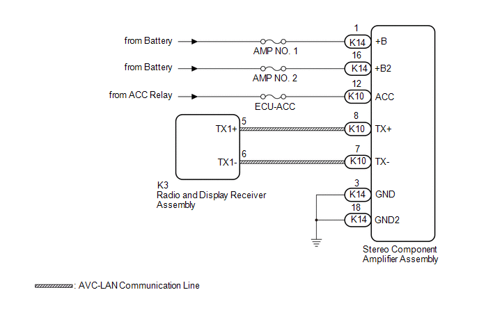
The radio and display receiver assembly and stereo component amplifier assembly are connected by the AVC-LAN communication line.
|
DTC No. | Detection Item |
DTC Detection Condition | Trouble Area |
|---|---|---|---|
|
B15D3 | Stereo Component Amplifier Disconnected |
When either of the following conditions is met:
|
|
HINT:
The radio and display receiver assembly is the master unit.
WIRING DIAGRAM
CAUTION / NOTICE / HINT
NOTICE:
- Inspect the fuses for circuits related to this system before performing the following procedure.
- Depending on the parts that are replaced during vehicle inspection or maintenance, performing initialization, registration or calibration may be needed. Refer to Precaution for Audio and Visual System.
Click here
.gif)
- When replacing the radio and display receiver assembly, always replace it with a new one. If a radio and display receiver assembly which was installed to another vehicle is used, the following may occur:
- A communication malfunction DTC may be stored.
- The radio and display receiver assembly may not operate normally.
PROCEDURE
|
1. | CHECK DTC |
(a) If DTC B15C3 is output, perform troubleshooting for DTC B15C3 first.
|
Result | Proceed to |
|---|---|
|
DTC B15C3 is not output. |
A |
| DTC B15C3 is output. |
B |
| B |
.gif) | GO TO DTC B15C3
|
|
.gif)
| 2. |
CHECK OPTIONAL COMPONENTS (INCLUDING ASSOCIATED WIRING) |
(a) Check that optional components (including associated wiring) which generate radio waves are not installed.
|
Result | Proceed to |
|---|---|
|
Optional components (including associated wiring) are installed. |
A |
| Optional components (including associated wiring) are not installed. |
B |
HINT:
- Electrical noise from radio waves generated by optional components or the wiring for those components may affect AVC-LAN communication.
- This DTC may be stored when an AVC-LAN communication error occurs due to electrical noise.
| B | | GO TO STEP 4 |
|
| 3. |
REMOVE OPTIONAL COMPONENTS (INCLUDING ASSOCIATED WIRING) |
(a) Remove optional components (including associated wiring).
NOTICE:
Do not remove optional components or associated wiring without the permission of the customer.
|
| 4. |
CHECK DTC |
(a) Clear the DTCs.
Body Electrical > Navigation System > Clear DTCs(b) Recheck for DTCs and check that no DTCs are output.
Body Electrical > Navigation System > Trouble CodesOK:
No DTCs are output.
| OK | |
END |
|
| 5. |
CHECK HARNESS AND CONNECTOR (STEREO COMPONENT AMPLIFIER ASSEMBLY POWER SOURCE) |
(a) Disconnect the K14 and K10 stereo component amplifier assembly connectors.
(b) Measure the resistance according to the value(s) in the table below.
Standard Resistance:
|
Tester Connection | Condition |
Specified Condition |
|---|---|---|
|
K14-3 (GND) - Body ground |
Always | Below 1 Ω |
|
K14-18 (GND2) - Body ground |
Always | Below 1 Ω |
(c) Measure the voltage according to the value(s) in the table below.
Standard Voltage:
|
Tester Connection | Condition |
Specified Condition |
|---|---|---|
|
K14-1 (+B) - K14-3 (GND) |
Always | 11 to 14 V |
|
K14-16 (+B2) - K14-3 (GND) |
Always | 11 to 14 V |
|
K10-12 (ACC) - K14-3 (GND) |
Ignition switch ACC | 11 to 14 V |
| NG | | REPAIR OR REPLACE HARNESS OR CONNECTOR |
|
| 6. |
CHECK HARNESS AND CONNECTOR (RADIO AND DISPLAY RECEIVER ASSEMBLY - STEREO COMPONENT AMPLIFIER ASSEMBLY) |
(a) Disconnect the K3 radio and display receiver assembly connector.
(b) Disconnect the K10 stereo component amplifier assembly connector.
(c) Measure the resistance according to the value(s) in the table below.
Standard Resistance:
|
Tester Connection | Condition |
Specified Condition |
|---|---|---|
|
K3-5 (TX1+) - K10-8 (TX+) |
Always | Below 1 Ω |
|
K3-6 (TX1-) - K10-7 (TX-) |
Always | Below 1 Ω |
|
K3-5 (TX1+) or K10-8 (TX+) - Body ground |
Always | 10 kΩ or higher |
|
K3-6 (TX1-) or K10-7 (TX-) - Body ground |
Always | 10 kΩ or higher |
| NG | | REPAIR OR REPLACE HARNESS OR CONNECTOR |
|
| 7. |
REPLACE STEREO COMPONENT AMPLIFIER ASSEMBLY |
(a) Replace the stereo component amplifier assembly with a new or known good one.
Click here
(b) Clear the DTCs.
Body Electrical > Navigation System > Clear DTCs(c) Recheck for DTCs and check that no DTCs are output.
Body Electrical > Navigation System > Trouble CodesOK:
No DTCs are output.
| OK | |
END |
| NG | | REPLACE RADIO AND DISPLAY RECEIVER ASSEMBLY
|
READ NEXT:
 Telematics Transceiver Disconnected (B15DB)
DESCRIPTION If the radio and display receiver assembly cannot detect the DCM (telematics transceiver) for a certain period of time (90 seconds) after the ignition switch is turned to ACC and the radio
Air Conditioner ECU Vehicle Information Reading/Writing Processor Malfunction (B15F5)
DESCRIPTION This DTC is stored when items controlled by the air conditioning amplifier assembly cannot be customized via the audio and visual system vehicle customization screen.
HINT: The air condi
Main Body ECU Vehicle Information Reading/Writing Process Malfunction (B15F6)
DESCRIPTION This DTC is stored when items controlled by the main body ECU (multiplex network body ECU) cannot be customized via the audio and visual system vehicle customization screen.
HINT: The ma
SEE MORE:
Radio Receiver Power Source Circuit
DESCRIPTION This is the power source circuit to operate the radio and display receiver assembly. WIRING DIAGRAM
CAUTION / NOTICE / HINT
NOTICE: Inspect the fuses for circuits related to this system before performing the following procedure. PROCEDURE
1.
CHECK HARNESS AND CONNECTOR (R
Replacement
REPLACEMENT PROCEDURE 1. REMOVE FRONT WHEEL OPENING EXTENSION PAD RH
Click here
2. REMOVE FRONT WHEEL OPENING EXTENSION PAD LH Click here
3. REMOVE NO. 1 ENGINE UNDER COVER
Click here
4. REMOVE NO. 2 ENGINE UNDER COVER ASSEMBLY Click here
5. DRAIN TRANSFER OIL Cli
