Toyota Camry (XV70): Telematics Transceiver Disconnected (B15DB)
DESCRIPTION
If the radio and display receiver assembly cannot detect the DCM (telematics transceiver) for a certain period of time (90 seconds) after the ignition switch is turned to ACC and the radio and display receiver assembly confirms that the information is missing by checking past DCM (telematics transceiver) recognition information (registered information), this DTC will be stored.
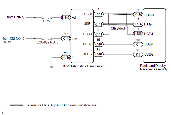
The telematics system uses USB communication between devices. If an open, short, short to +B or short to ground occurs in the USB circuit, communication is interrupted and the telematics system will not operate normally.
|
DTC No. | Detection Item |
DTC Detection Condition | Trouble Area |
|---|---|---|---|
|
B15DB | Telematics Transceiver Disconnected |
DCM (telematics transceiver) disconnected |
|
HINT:
This DTC may be stored due to environmental reasons such as electrical noise or interference.
WIRING DIAGRAM
CAUTION / NOTICE / HINT
NOTICE:
- Depending on the parts that are replaced during vehicle inspection or maintenance, performing initialization, registration or calibration may be needed. Refer to Precaution for Audio and Visual System.
Click here
.gif)
- When replacing the radio and display receiver assembly, always replace it with a new one. If a radio and display receiver assembly which was installed to another vehicle is used, the following may occur:
- A communication malfunction DTC may be stored.
- The radio and display receiver assembly may not operate normally.
- Inspect the fuses for circuits related to this system before performing the following procedure.
- Before replacing the DCM (telematics transceiver), refer to Registration.
Click here
PROCEDURE
|
1. | CHECK HARNESS AND CONNECTOR (DCM (TELEMATICS TRANSCEIVER) POWER SOURCE) |
(a) Disconnect the K140 DCM (telematics transceiver) connector.
(b) Measure the resistance according to the value(s) in the table below.
Standard Resistance:
|
Tester Connection | Condition |
Specified Condition |
|---|---|---|
|
K140-20 (E) - Body ground |
Always | Below 1 Ω |
(c) Measure the voltage according to the value(s) in the table below.
Standard Voltage:
|
Tester Connection | Condition |
Specified Condition |
|---|---|---|
|
K140-1 (+B) - K140-20 (E) |
Always | 11 to 14 V |
|
K140-19 (IG2) - K140-20 (E) |
Ignition switch ON | 11 to 14 V |
| NG | .gif) | REPAIR OR REPLACE HARNESS OR CONNECTOR |
|
.gif)
| 2. |
INSPECT RADIO AND DISPLAY RECEIVER ASSEMBLY |
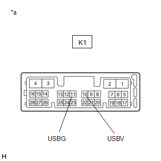
(a) Disconnect the K1 radio and display receiver assembly connector.
| (b) Measure the resistance according to the value(s) in the table below. Standard Resistance:
|
|
(c) Measure the voltage according to the value(s) in the table below.
Standard Voltage:
|
Tester Connection | Condition |
Specified Condition |
|---|---|---|
|
K1-10 (USBV) - K1-11 (USBG) |
Ignition switch ON | 4.75 to 5.25 V |
| NG | | REPLACE RADIO AND DISPLAY RECEIVER ASSEMBLY
|
|
| 3. |
CHECK HARNESS AND CONNECTOR (RADIO AND DISPLAY RECEIVER ASSEMBLY - DCM (TELEMATICS TRANSCEIVER)) |
(a) Disconnect the K1 radio and display receiver assembly connector.
(b) Disconnect the K140 DCM (telematics transceiver) connector.
(c) Measure the resistance according to the value(s) in the table below.
Standard Resistance:
|
Tester Connection | Condition |
Specified Condition |
|---|---|---|
|
K1-10 (USBV) - K140-15 (USBV) |
Always | Below 1 Ω |
|
K1-11 (USBG) - K140-31 (USBG) |
Always | Below 1 Ω |
|
K1-10 (USBV) or K140-15 (USBV) - Body ground |
Always | 10 kΩ or higher |
|
K1-11 (USBG) or K140-31 (USBG) - Body ground |
Always | 10 kΩ or higher |
| NG | | REPAIR OR REPLACE HARNESS OR CONNECTOR |
|
| 4. |
CHECK HARNESS AND CONNECTOR (RADIO AND DISPLAY RECEIVER ASSEMBLY - DCM (TELEMATICS TRANSCEIVER)) |
(a) Check the installation condition.
(1) Check the USB communication lines between the radio and display receiver assembly and DCM (telematics transceiver) for any installation or connection problems.
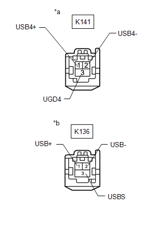
(b) Disconnect the K136 radio and display receiver assembly connector.
(c) Disconnect the K141 DCM (telematics transceiver) connector.
| (d) Measure the resistance according to the value(s) in the table below. Standard Resistance:
|
|
| NG | | REPAIR OR REPLACE HARNESS OR CONNECTOR |
|
| 5. |
REPLACE DCM (TELEMATICS TRANSCEIVER) |
(a) Replace the DCM (telematics transceiver) with a new one.
Click here
(b) Clear the DTCs.
Body Electrical > Navigation System > Clear DTCs(c) Turn the ignition switch off.
(d) Turn the ignition switch to IG and wait for 90 seconds.
(e) Recheck for DTCs and check that no DTCs are output.
Body Electrical > Navigation System > Trouble CodesOK:
No DTCs are output.
| OK | |
END |
| NG | | REPLACE RADIO AND DISPLAY RECEIVER ASSEMBLY
|
READ NEXT:
 Air Conditioner ECU Vehicle Information Reading/Writing Processor Malfunction (B15F5)
DESCRIPTION This DTC is stored when items controlled by the air conditioning amplifier assembly cannot be customized via the audio and visual system vehicle customization screen.
HINT: The air condi
Main Body ECU Vehicle Information Reading/Writing Process Malfunction (B15F6)
DESCRIPTION This DTC is stored when items controlled by the main body ECU (multiplex network body ECU) cannot be customized via the audio and visual system vehicle customization screen.
HINT: The ma
Certification ECU Vehicle Information Reading/Writing Process Malfunction (B15F7)
DESCRIPTION This DTC is stored when items controlled by the certification ECU (smart key ECU assembly) cannot be customized via the audio and visual system vehicle customization screen.
HINT: The ce
SEE MORE:
For safe driving
For safe driving, adjust the seat and mirror to an appropriate
position before driving.
Correct driving posture
Adjust the angle of the seatback
so that you are sitting
straight up and so that you do
not have to lean forward to
steer.
Adjust the seat so that you can
depress the ped
Removal
REMOVAL CAUTION / NOTICE / HINT
HINT:
Use the same procedure for the RH side and LH side.
The following procedure is for the LH side.
PROCEDURE 1. PRECAUTION Click here
2. RELEASE PARKING BRAKE (a) Move the shift lever to P.
(b) Turn the engine switch on (IG). (c) Operate the ele
