Toyota Camry (XV70): Radio Receiver Power Source Circuit
DESCRIPTION
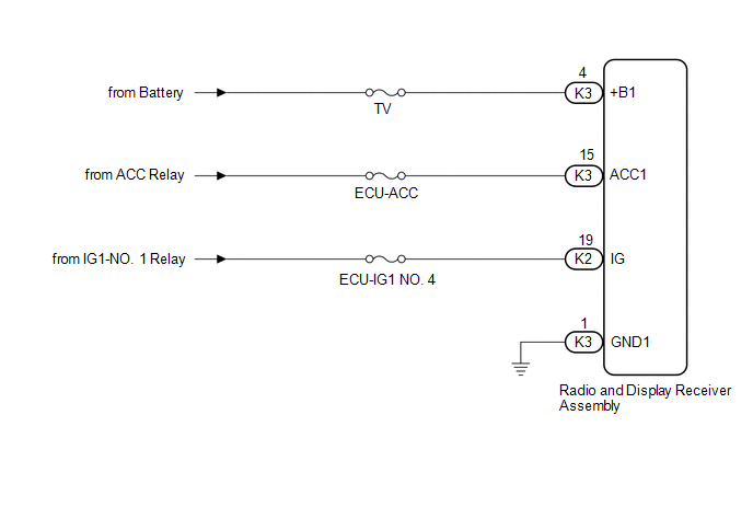
This is the power source circuit to operate the radio and display receiver assembly.
WIRING DIAGRAM
CAUTION / NOTICE / HINT
NOTICE:
Inspect the fuses for circuits related to this system before performing the following procedure.
PROCEDURE
| 1. |
CHECK HARNESS AND CONNECTOR (RADIO AND DISPLAY RECEIVER ASSEMBLY POWER SOURCE) |
(a) Disconnect the K3 and K2 radio and display receiver assembly connectors.
(b) Measure the resistance according to the value(s) in the table below.
Standard Resistance:
|
Tester Connection | Condition |
Specified Condition |
|---|---|---|
|
K3-1 (GND1) - Body ground |
Always | Below 1 Ω |
(c) Measure the voltage according to the value(s) in the table below.
Standard Voltage:
|
Tester Connection | Condition |
Specified Condition |
|---|---|---|
|
K3-4 (+B1) - K3-1 (GND1) |
Always | 11 to 14 V |
|
K3-15 (ACC1) - K3-1 (GND1) |
Engine switch on (ACC) |
11 to 14 V |
|
K2-19 (IG) - K3-1 (GND1) |
Engine switch on (IG) |
11 to 14 V |
| OK | .gif) | PROCEED TO NEXT SUSPECTED AREA SHOWN IN PROBLEM SYMPTOMS TABLE
|
.gif)
| NG | | REPAIR OR REPLACE HARNESS OR CONNECTOR |
READ NEXT:
 Blind Spot Monitor Sensor
ComponentsCOMPONENTS ILLUSTRATION
*1 BLIND SPOT MONITOR SENSOR LH
*2 BLIND SPOT MONITOR SENSOR RH
*3 REAR BUMPER ASSEMBLY
- -
N*m (kgf*cm, ft.*lbf)
SEE MORE:
If you have a flat tire
Your vehicle is equipped with a spare tire. The flat tire can be
replaced with the spare tire.
WARNING
■If you have a flat tire
Do not continue driving with a flat tire.
Driving even a short distance with a flat tire can damage the tire and the
wheel beyond repair, which could result in an
Left Electric Parking Brake Actuator Control (C060B00,C060B11)
DESCRIPTION
DTC No. Detection Item
DTC Detection Condition Trouble Area
Memory Note
C060B00 Left Electric Parking Brake Actuator Control
Diagnosis Condition:
-
Malfunction Status:
When the ECU power supply is normal, a malfunction in the electri
