Toyota Camry (XV70): Blind Spot Monitor Sensor
Components
COMPONENTS
ILLUSTRATION
|
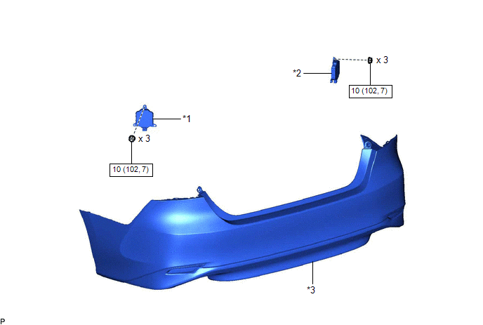
*1 | BLIND SPOT MONITOR SENSOR LH |
*2 | BLIND SPOT MONITOR SENSOR RH |
|
*3 | REAR BUMPER ASSEMBLY |
- | - |
.png) |
N*m (kgf*cm, ft.*lbf) : Specified torque |
- | - |
Removal
REMOVAL
CAUTION / NOTICE / HINT
The necessary procedures (adjustment, calibration, initialization, or registration) that must be performed after parts are removed and installed, or replaced during blind spot monitor sensor removal/installation are shown below.
Necessary Procedure After Parts Removed/Installed/Replaced|
Replaced Part or Performed Procedure |
Necessary Procedure | Effect/Inoperative Function when Necessary Procedure not Performed |
Link |
|---|---|---|---|
| Blind spot monitor sensor |
Blind spot monitor beam axis adjustment |
|
|
|
Rear bumper assembly (w/ Parking Support Brake System) |
|
|
|
PROCEDURE
1. REMOVE REAR BUMPER ASSEMBLY
Click here
.gif)
2. REMOVE BLIND SPOT MONITOR SENSOR LH
| (a) Disconnect the connector. |
|
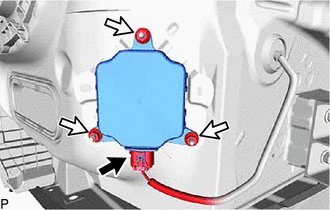
(b) Remove the 3 nuts and blind spot monitor sensor LH.
NOTICE:
Replace the blind spot monitor sensor LH if it has been dropped or subjected to a severe impact.
3. REMOVE BLIND SPOT MONITOR SENSOR RH
| (a) Disconnect the connector. |
|
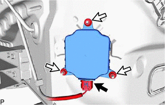
(b) Remove the 3 nuts and blind spot monitor sensor RH.
NOTICE:
Replace the blind spot monitor sensor RH if it has been dropped or subjected to a severe impact.
Installation
INSTALLATION
CAUTION / NOTICE / HINT
NOTICE:
- Avoid any impact to the blind spot monitor sensor.
- Do not drop the blind spot monitor sensor. If it is dropped, replace it with a new one.
HINT:
- The blind spot monitor beam axis confirmation is performed to confirm whether the sensor beam axis is correct, and to adjust the beam axis by using a reflector.
- The blind spot monitor sensor installation condition inspection is performed to confirm whether the sensor is perpendicular to the floor surface (+/-2.2
READ NEXT:
 Precaution
PRECAUTION PRECAUTION FOR DISCONNECTING CABLE FROM NEGATIVE BATTERY TERMINAL
NOTICE: When disconnecting the cable from the negative (-) battery terminal, initialize the following systems after the c
Parts Location
PARTS LOCATION ILLUSTRATION
*1 OUTER REAR VIEW MIRROR ASSEMBLY WITH COVER RH
*2 OUTER REAR VIEW MIRROR ASSEMBLY WITH COVER LH
*3 BRAKE ACTUATOR ASSEMBLY - SKID CONTROL EC
SEE MORE:
Precaution
PRECAUTION IGNITION SWITCH EXPRESSION HINT:
The type of ignition switch used on this model differs depending on the specifications of the vehicle. The expressions listed in the table below are used in this section.
Expression Ignition Switch (Position)
Engine Switch (Condition)
Terminals Of Ecu
TERMINALS OF ECU HINT: Check from the rear of the connector while it is connected to the components.
RADIO AND DISPLAY RECEIVER ASSEMBLY
Terminal No. (Symbol) Wiring Color
Terminal Description Condition
Specified Condition
K4-1 (FR+) - K3-1 (GND1)
W - BR Soun
