Toyota Camry (XV70): Removal
REMOVAL
CAUTION / NOTICE / HINT
NOTICE:
- Immediately after installing the front disc brake pads, the braking performance may be reduced. Always perform a road test in a safe place while paying attention to the surroundings.
- After replacing the front disc brake pads, the brake pedal may feel soft due to clearance between the front disc brake pads and front disc. Depress the brake pedal several times until the brake pedal feels firm.
- After replacing the front disc brake pads, always perform a road test to check the braking performance and check for vibrations.
HINT:
- Use the same procedure for the RH side and LH side.
- The following procedure is for the LH side.
PROCEDURE
1. REMOVE FRONT WHEEL
Click here .gif)
2. REMOVE FRONT DISC BRAKE PAD
CAUTION:
- Be careful not to get pinched by the front disc brake cylinder assembly or other parts when removing the front disc brake pads.
- After lifting up the front disc brake cylinder assembly, secure it in place before performing any work on it.
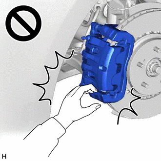
- The front disc brake cylinder assembly could fall, pinching hands or fingers and causing injury.
| (a) Hold the front disc brake cylinder slide pin (lower side) and remove the bolt. NOTICE: Do not kink or damage the brake line. |
|
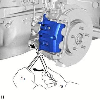
(b) Pull the front disc brake cylinder assembly upward.
| (c) Remove the 2 anti-squeal springs. |
|
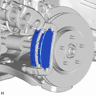
(d) Remove the 2 front disc brake pads from the front disc brake cylinder mounting.
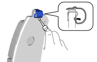
3. REMOVE FRONT DISC BRAKE ANTI-SQUEAL SHIM KIT
(a) Remove the front No. 1 disc brake anti-squeal shim and front No. 2 disc brake anti-squeal shim from each front disc brake pad.
| (b) Using a screwdriver, remove the front disc brake pad wear indicator plate from each front disc brake pad. |
|
READ NEXT:
 Installation
INSTALLATION CAUTION / NOTICE / HINT
NOTICE:
Immediately after installing the front disc brake pads, the braking performance may be reduced. Always perform a road test in a safe place while payi
Front Side Marker Light Bulb
ComponentsCOMPONENTS ILLUSTRATION
*1 FRONT SIDE MARKER LIGHT BULB
- - RemovalREMOVAL CAUTION / NOTICE / HINT
HINT:
Use the same procedure for the RH side and LH side.
Front Turn Signal Light Bulb
ComponentsCOMPONENTS ILLUSTRATION
*1 FRONT TURN SIGNAL LIGHT BULB
- - RemovalREMOVAL CAUTION / NOTICE / HINT
HINT:
Use the same procedure for the RH side and LH side.
SEE MORE:
Removal
REMOVAL CAUTION / NOTICE / HINT
The necessary procedures (adjustment, calibration, initialization, or registration) that must be performed after parts are removed and installed, or replaced during clearance warning ECU assembly removal/installation are shown below. Necessary Procedure After Parts
Components
COMPONENTS ILLUSTRATION
*A for Front Passenger Side
*B for Driver Side
*C w/o Courtesy Light
*D w/ Courtesy Light
*1 COURTESY LIGHT ASSEMBLY
*2 FRONT ARMREST ASSEMBLY
*3 FRONT DOOR ARMREST COVER SUB-ASSEMBLY
*4 FRONT DOOR LOWE
© 2023-2025 Copyright www.tocamry.com
