Toyota Camry (XV70): Removal
REMOVAL
CAUTION / NOTICE / HINT
The necessary procedures (adjustment, calibration, initialization or registration) that must be performed after parts are removed and installed, or replaced during amplifier antenna assembly removal/installation are shown below.
Necessary Procedure After Parts Removed/Installed/Replaced|
Replaced Part or Performed Procedure |
Necessary Procedures | Effect/Inoperative Function when Necessary Procedure not Performed |
Link |
|---|---|---|---|
| Disconnect cable from negative battery terminal |
Perform steering sensor zero point calibration |
Lane Tracing Assist System |
|
|
Pre-collision System | |||
|
Memorize steering angle neutral point |
Parking Assist Monitor System |
| |
|
Panoramic View Monitor System |
|
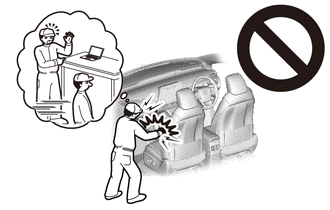
CAUTION:
Some of these service operations affect the SRS airbag system. Read the precautionary notices concerning the SRS airbag system before servicing.
Click here

PROCEDURE
1. PRECAUTION
NOTICE:
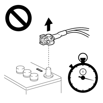
After turning the ignition switch off, waiting time may be required before disconnecting the cable from the negative (-) battery terminal. Therefore, make sure to read the disconnecting the cable from the negative (-) battery terminal notices before proceeding with work.
Click here
2. DISCONNECT CABLE FROM NEGATIVE BATTERY TERMINAL
for A25A-FKS:
Click here
for 2GR-FKS:
Click here
CAUTION:
- Wait at least 90 seconds after disconnecting the cable from the negative (-) battery terminal to disable the SRS system.
- If an airbag deploys for any reason, it may cause a serious injury.
3. REMOVE REAR SEAT ASSEMBLY (for Fixed Seat Type)
Click here
4. REMOVE REAR SEAT CUSHION ASSEMBLY (for Fold Down Seat Type)
Click here
5. REMOVE REAR SEAT CUSHION LOCK HOOK (for Fold Down Seat Type)
Click here
6. DISCONNECT REAR DOOR OPENING TRIM WEATHERSTRIP LH
Click here
7. REMOVE REAR SIDE SEATBACK ASSEMBLY LH (for Fold Down Seat Type)
Click here
8. DISCONNECT REAR DOOR OPENING TRIM WEATHERSTRIP RH
HINT:
Use the same procedure as for the LH side.
9. REMOVE REAR SIDE SEATBACK ASSEMBLY RH (for Fold Down Seat Type)
HINT:
Use the same procedure as for the LH side.
10. REMOVE INNER ROOF SIDE GARNISH LH
Click here
11. REMOVE INNER ROOF SIDE GARNISH RH
HINT:
Use the same procedure as for the LH side.
12. REMOVE NO. 2 AMPLIFIER ANTENNA ASSEMBLY
| (a) Disconnect the 2 connectors. |
|
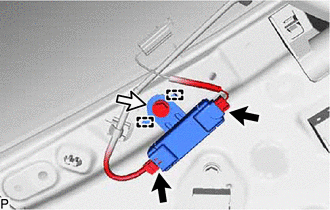
(b) Remove the bolt.
(c) Disengage the 2 guides to remove the No. 2 amplifier antenna assembly.
13. REMOVE NO. 1 AMPLIFIER ANTENNA ASSEMBLY
HINT:
Use the same procedure as for the No. 2 amplifier antenna assembly.
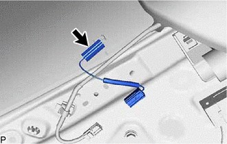
14. REMOVE ANTENNA CORD SUB-ASSEMBLY
| (a) Disconnect the connector to remove the antenna cord sub-assembly. HINT: Use the same procedure for the RH side and LH side. |
|
READ NEXT:
 Installation
INSTALLATION PROCEDURE 1. INSTALL ANTENNA CORD SUB-ASSEMBLY
(a) Connect the connector to install the antenna cord sub-assembly. HINT:
Use the same procedure for the RH side and LH side. 2. INSTALL
Precaution
PRECAUTION PRECAUTION FOR DISCONNECTING CABLE FROM NEGATIVE BATTERY TERMINAL
NOTICE:
After the ignition switch is turned off, the radio and display receiver assembly records various types of mem
SEE MORE:
Emergency flashers
The emergency flashers are used to warn other drivers when the
vehicle has to be stopped on the road due to a breakdown, etc.
Press the switch.
All the turn signal lights will flash.
To turn them off, press the switch
once again.
■Emergency flashers
If the emergency flashers are us
Fuel Pump Control Circuit
DESCRIPTION The fuel pump (for low pressure side) circuit consists of the ECM, fuel pump (for low pressure side) and fuel pump control ECU (which operates the fuel pump (for low pressure side)). Based on the engine output, the ECM determines the fuel pump speed. The speed is then converted to a duty
