Toyota Camry (XV70): Removal
REMOVAL
CAUTION / NOTICE / HINT
The necessary procedures (adjustment, calibration, initialization or registration) that must be performed after parts are removed and installed, or replaced during brake actuator assembly removal/installation are shown below.
Necessary Procedures After Parts Removed/Installed/Replaced|
Replaced Part or Performed Procedure |
Necessary Procedure | Effect/Inoperative Function when Necessary Procedure not Performed |
Link |
|---|---|---|---|
|
*1: w/o Electric Parking Brake System
*2: w/ Electric Parking Brake System | |||
|
Disconnect cable from negative battery terminal |
Perform steering sensor zero point calibration |
Lane tracing assist system |
|
|
Pre-collision system | |||
|
Memorize steering angle neutral point |
Parking assist monitor system |
| |
|
Panoramic view monitor system |
| ||
|
Replacement of brake actuator assembly |
Operate the electric parking brake switch*2 |
Electric parking brake system |
|
|
Perform acceleration sensor zero point calibration and system information memorization |
|
| |
PROCEDURE
1. PRECAUTION
NOTICE:
After turning the ignition switch off, waiting time may be required before disconnecting the cable from the negative (-) battery terminal. Therefore, make sure to read the disconnecting the cable from the negative (-) battery terminal notices before proceeding with work.
Click here .gif)
2. DISCONNECT CABLE FROM NEGATIVE BATTERY TERMINAL
for A25A-FKS: Click here
for 2GR-FKS: Click here
NOTICE:
When disconnecting the cable, some systems need to be initialized after the cable is reconnected.
Click here
3. DRAIN BRAKE FLUID
NOTICE:
If brake fluid leaks onto any painted surface, immediately wash it off.
4. REMOVE FRONT WHEEL RH
Click here
5. REMOVE COWL TOP VENTILATOR LOUVER SUB-ASSEMBLY
Click here
6. REMOVE FRONT CENTER UPPER SUSPENSION BRACE SUB-ASSEMBLY
| (a) Disconnect the connector. |
|
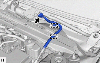
(b) Disengage the 2 clamps and separate the wire harness.
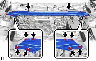
| (c) Remove the 6 bolts, 4 nuts and front center upper suspension brace sub-assembly. |
|
7. REMOVE BRAKE ACTUATOR WITH BRACKET
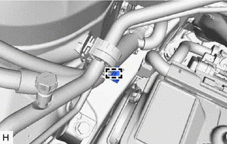
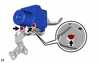
(a) Release the lock lever and disconnect the connector from the brake actuator assembly.
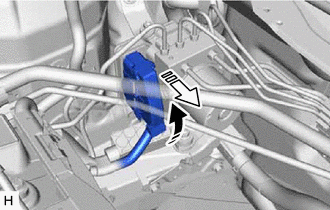
 |
Release the lock lever |
 |
Disconnect the connector |
NOTICE:
Be careful not to allow any brake fluid to enter the connector.
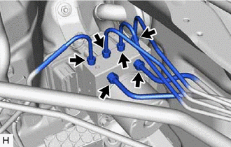
| (b) Use tags or make a memo to identify the places to reconnect the brake lines. |
|
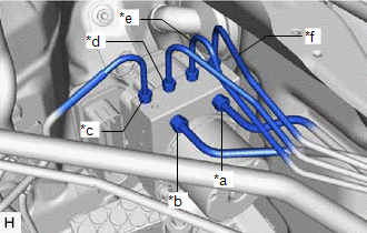
| (c) Using a union nut wrench, disconnect the 6 brake lines from the brake actuator assembly. NOTICE:
|
|
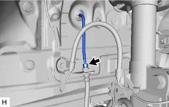
| (d) Using a union nut wrench, disconnect the front No. 3 brake tube while holding the front flexible hose with a wrench. NOTICE:
|
|
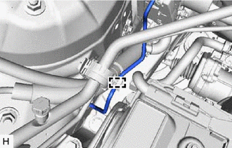
| (e) Disengage the clamp and separate the front No. 3 brake tube. NOTICE: Do not kink or damage the front No. 3 brake tube. |
|
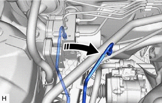
| (f) Move aside the front No. 3 brake tube as shown in the illustration. NOTICE: Do not apply excessive force to the front No. 3 brake tube. |
|
| (g) Disengage the clamp and remove the brake tube clamp. |
|
(h) Apply protective tape to the vehicle body as shown in the illustration.
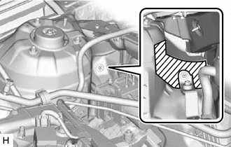
.png) |
Protective Tape |
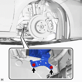
| (i) Remove the 2 bolts. HINT: Insert the tool from the bottom of the vehicle. |
|
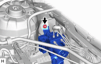
| (j) Remove the nut and brake actuator with bracket. NOTICE:
HINT: Remove the brake actuator with bracket while avoiding the brake lines. |
|
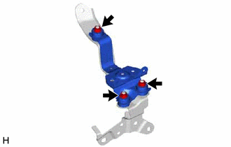
8. REMOVE BRAKE ACTUATOR ASSEMBLY
| (a) Remove the 3 bolts and brake actuator assembly from the brake actuator bracket assembly. NOTICE:
|
|
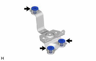
9. REMOVE NO. 2 BRAKE ACTUATOR CASE COLLAR
HINT:
Perform this procedure only when replacement of the No. 2 brake actuator case collars is necessary.
| (a) Remove the 3 nuts. |
|
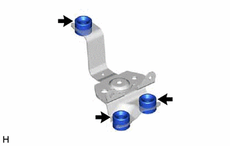
| (b) Remove the 3 No. 2 brake actuator case collars from the brake actuator bracket cushion. |
|
10. REMOVE BRAKE ACTUATOR BRACKET CUSHION
HINT:
Perform this procedure only when replacement of the brake actuator bracket cushions is necessary.
| (a) Remove the 3 brake actuator bracket cushions from the brake actuator bracket. |
|
READ NEXT:
 Installation
INSTALLATION CAUTION / NOTICE / HINT w/ Electric Parking Brake System:
HINT: The parking brake indicator light blinks (red) when the engine switch is turned on after replacing the brake actuator ass
Brake Hold Switch
ComponentsCOMPONENTS ILLUSTRATION
*1 BRAKE HOLD SWITCH (ELECTRIC PARKING BRAKE SWITCH ASSEMBLY)
- - RemovalREMOVAL PROCEDURE
1. PRECAUTION Click here
2. REMOVE REAR UPPER
SEE MORE:
Problem Symptoms Table
PROBLEM SYMPTOMS TABLE
NOTICE:
Depending on the parts that are replaced during vehicle inspection or maintenance, performing initialization, registration or calibration may be needed. Refer to Precaution for Navigation System.
Click here
When replacing the radio and display receiver asse
ABS Pump Motor Control Circuit Short to Ground (C052C11,C052C13,C052F14,C142719)
DESCRIPTION The ABS motor relay is built into the brake actuator assembly.
When the skid control ECU (brake actuator assembly) operates ABS, TRAC, VSC or brake assist, the ABS motor relay turns ON and drives the motor pump built into the brake actuator assembly.
DTC No. Detection Item
