Toyota Camry (XV70): Removal
REMOVAL
CAUTION / NOTICE / HINT
The necessary procedures (adjustment, calibration, initialization or registration) that must be performed after parts are removed and installed, or replaced during brake master cylinder sub-assembly removal/installation are shown below.
Necessary Procedures After Parts Removed/Installed/Replaced|
Replaced Part or Performed Procedure |
Necessary Procedure | Effect/Inoperative Function when Necessary Procedure not Performed |
Link |
|---|---|---|---|
|
Disconnect cable from negative battery terminal |
Perform steering sensor zero point calibration |
Lane tracing assist system |
|
|
Pre-collision system | |||
|
Memorize steering angle neutral point |
Parking assist monitor system |
| |
|
Panoramic view monitor system |
|
CAUTION / NOTICE / HINT
NOTICE:
Make sure to release vacuum from the brake booster assembly before removing the brake master cylinder sub-assembly from the brake booster assembly.
PROCEDURE
1. PRECAUTION
NOTICE:
After turning the ignition switch off, waiting time may be required before disconnecting the cable from the negative (-) battery terminal. Therefore, make sure to read the disconnecting the cable from the negative (-) battery terminal notices before proceeding with work.
Click here .gif)
2. REMOVE BATTERY
for A25A-FKS: Click here
for 2GR-FKS: Click here
3. DRAIN BRAKE FLUID
NOTICE:
If brake fluid leaks onto any painted surface, immediately wash it off.
4. REMOVE BRAKE MASTER CYLINDER SUB-ASSEMBLY
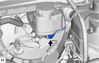
| (a) Disconnect the connector from the brake master cylinder sub-assembly. |
|
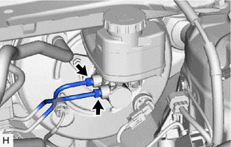
| (b) Using a union nut wrench, disconnect the 2 brake lines from the brake master cylinder sub-assembly. NOTICE:
|
|
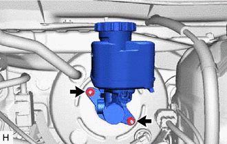
| (c) Remove the 2 nuts and brake master cylinder sub-assembly from the brake booster assembly. NOTICE:
|
|
5. REMOVE BRAKE MASTER CYLINDER O-RING
(a) Remove the brake master cylinder O-ring from the brake master cylinder sub-assembly.
READ NEXT:
 Disassembly
DISASSEMBLY PROCEDURE 1. REMOVE BRAKE MASTER CYLINDER STRAIGHT PIN
(a) Secure the brake master cylinder sub-assembly in a vise. NOTICE:
Place aluminum plates on the vise to prevent damage to the b
Inspection
INSPECTION PROCEDURE 1. INSPECT AND ADJUST BRAKE BOOSTER PUSH ROD
NOTICE: Make the adjustment with no vacuum in the brake booster assembly. (Depress the brake pedal several times with the engine sto
Reassembly
REASSEMBLY PROCEDURE 1. INSTALL BRAKE MASTER CYLINDER RESERVOIR STRAINER
2. INSTALL BRAKE MASTER CYLINDER RESERVOIR FILLER CAP ASSEMBLY 3. INSTALL MASTER CYLINDER RESERVOIR GROMMET
(a) Apply a lig
SEE MORE:
Steering Angle Sensor
ComponentsCOMPONENTS ILLUSTRATION
*1 STEERING SENSOR
*2 SPIRAL CABLE SUB-ASSEMBLY RemovalREMOVAL CAUTION / NOTICE / HINT
The necessary procedures (adjustment, calibration, initialization or registration) that must be performed after parts are removed and installed, or replac
On-vehicle Inspection
ON-VEHICLE INSPECTION CAUTION / NOTICE / HINT
CAUTION: To prevent injury due to contact with an operating V-ribbed belt or cooling fan, keep your hands and clothing away from the V-ribbed belt and cooling fans when working in the engine compartment with the engine running or the engine switch on
