Toyota Camry (XV70): Removal
REMOVAL
CAUTION / NOTICE / HINT
The necessary procedures (adjustment, calibration, initialization, or registration) that must be performed after parts are removed and installed, or replaced during rear axle carrier sub-assembly removal/installation are shown below.
Necessary Procedures After Parts Removed/Installed/Replaced|
Replaced Part or Performed Procedure |
Necessary Procedure | Effect/Inoperative Function when Necessary Procedure not Performed |
Link |
|---|---|---|---|
| Rear wheel alignment adjustment |
|
|
|
|
Suspension, tires, etc. (The vehicle height changes because of suspension or tire replacement) |
Rear television camera assembly optical axis (Back camera position setting) |
Parking assist monitor system |
|
| Panoramic view monitor system |
|
HINT:
- Use the same procedure for the RH side and LH side.
- The following procedure is for the LH side.
PROCEDURE
1. REMOVE REAR WHEEL
Click here
.gif)
2. REMOVE REAR AXLE SHAFT NUT
Click here
3. SEPARATE NO. 2 PARKING BRAKE WIRE ASSEMBLY
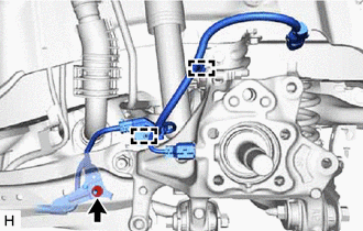
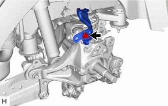
| (a) Disconnect the No. 2 parking brake wire assembly connector from the parking brake actuator assembly. NOTICE:
|
|
.png)
| (b) Using a screwdriver with its tip wrapped with protective tape, disconnect the No. 2 parking brake wire assembly connector from the rear skid control sensor. NOTICE:
|
|
| (c) Remove the nut, disengage the 2 clamps and separate the No. 2 parking brake wire assembly from the rear flexible hose bracket and rear trailing arm assembly. |
|
4. REMOVE REAR SKID CONTROL SENSOR
Click here
5. SEPARATE REAR FLEXIBLE HOSE
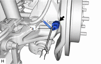
| (a) Remove the bolt and separate the rear flexible hose from the rear flexible hose bracket. |
|
.png)
6. SEPARATE REAR DISC BRAKE CALIPER ASSEMBLY
Click here
7. REMOVE REAR DISC
Click here
8. REMOVE REAR AXLE HUB AND BEARING ASSEMBLY
Click here
9. REMOVE REAR FLEXIBLE HOSE BRACKET
| (a) Remove the bolt and rear flexible hose bracket from the rear axle carrier sub-assembly. |
|
10. REMOVE REAR STABILIZER LINK ASSEMBLY
Click here
11. REMOVE REAR COIL SPRING
Click here
12. REMOVE REAR LOWER COIL SPRING INSULATOR
Click here
13. REMOVE REAR NO. 1 SUSPENSION ARM ASSEMBLY
Click here
14. REMOVE REAR AXLE CARRIER SUB-ASSEMBLY
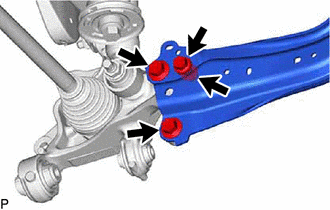
| (a) Loosen the 3 bolts and nut of the rear trailing arm assembly. |
|
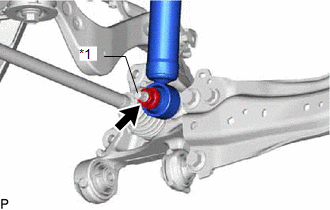
| (b) Loosen the nut of the rear shock absorber assembly. NOTICE: Hold the rear axle carrier pin while rotating the nut. |
|
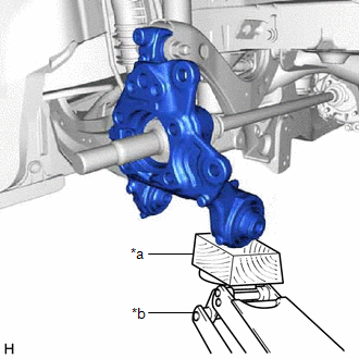
| (c) Using a jack and a wooden block, support the rear axle carrier sub-assembly. NOTICE:
|
|
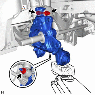
| (d) Loosen the bolt (A). NOTICE: Because the nut has its own stopper, do not turn the nut. Loosen the bolt with the nut secured. |
|
(e) Remove the 3 bolts, nut and separate the rear trailing arm assembly from the rear axle carrier sub-assembly.
(f) Remove the nut and plate washer, and separate the rear shock absorber assembly from the rear axle carrier sub-assembly.
NOTICE:
Hold the rear axle carrier pin while rotating the nut.
(g) Remove the bolt (A), nut and rear axle carrier sub-assembly from the rear upper control arm assembly.
NOTICE:
- Because the nut has its own stopper, do not turn the nut. Loosen the bolt with the nut secured.
- Use wire or an equivalent tool to keep the rear drive shaft assembly from hanging down.
READ NEXT:
 Installation
INSTALLATION CAUTION / NOTICE / HINT
HINT:
Use the same procedure for the RH side and LH side.
The following procedure is for the LH side.
PROCEDURE 1. TEMPORARILY INSTALL REAR AXLE CARR
Components
COMPONENTS ILLUSTRATION
*1 NO. 2 PARKING BRAKE WIRE ASSEMBLY
*2 REAR AXLE HUB AND BEARING ASSEMBLY
*3 REAR DISC
*4 REAR DISC BRAKE CALIPER ASSEMBLY
*5 R
SEE MORE:
Differential Oil Seal
ComponentsCOMPONENTS ILLUSTRATION
*1 DRIVE SHAFT BEARING BRACKET
*2 FRONT DRIVE SHAFT OIL SEAL LH
*3 FRONT DRIVE SHAFT OIL SEAL RH
- -
N*m (kgf*cm, ft.*lbf): Specified torque
● Non-reusable part
Do not apply lubricants
Installation
INSTALLATION PROCEDURE 1. INSTALL FUEL PIPE PLUG SUB-ASSEMBLY
(a) Install a new O-ring, No. 1 fuel injector back-up ring, No. 2 fuel injector back-up ring and No. 3 fuel injector back-up ring to the fuel pipe plug sub-assembly as shown in the illustration.
*1 Fuel Pipe Plug Sub-assemb
