Toyota Camry (XV70): Removal
REMOVAL
CAUTION / NOTICE / HINT
The necessary procedures (adjustment, calibration, initialization, or registration) that must be performed after parts are removed and installed, or replaced during rear differential carrier assembly removal/installation are shown below.
Necessary Procedures After Parts Removed/Installed/Replaced|
Replaced Part or Performed Procedure |
Necessary Procedure | Effect/Inoperative Function when Necessary Procedure not Performed |
Link |
|---|---|---|---|
| Rear wheel alignment adjustment |
|
|
|
|
Suspension, tires, etc. (The vehicle height changes because of suspension or tire replacement) |
Rear television camera assembly optical axis (Back camera position setting) |
Parking assist monitor system |
|
| Panoramic view monitor system |
| |
|
Exhaust system parts | Inspection after repair |
|
|
CAUTION:
To prevent burns, do not touch the engine, exhaust pipe or other high temperature components while the engine is hot.
.png)
PROCEDURE
1. DRAIN DIFFERENTIAL OIL
Click here
.gif)
2. REMOVE PROPELLER WITH CENTER BEARING SHAFT ASSEMBLY
Click here
3. REMOVE REAR STABILIZER BAR
Click here
4. REMOVE REAR DRIVE SHAFT ASSEMBLY LH
Click here
5. REMOVE REAR DRIVE SHAFT ASSEMBLY RH
HINT:
Use the same procedure described for the LH side.
6. REMOVE REAR DIFFERENTIAL CARRIER ASSEMBLY
(a) Disengage the 2 wire harness clamps to separate the wire harness.
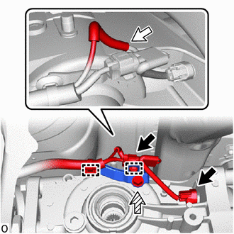
.png) |
Connector |
.png) |
Breather Tube |
.png) |
Bolt |
(b) Disconnect the 2 connectors.
(c) Remove the bolt and wire harness clamp bracket.
(d) Remove the breather tube.
(e) Support the rear differential carrier assembly with a transmission jack.
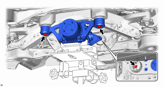
(f) Remove the 3 bolts and 2 rear lower differential mount stoppers.
(g) Slowly lower the jack and then tilt the rear differential carrier assembly.
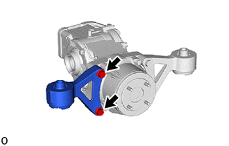
7. REMOVE REAR NO. 1 DIFFERENTIAL SUPPORT
(a) Remove the rear upper differential mount stopper from the rear No. 1 differential support.
| (b) Remove the 2 bolts and rear No. 1 differential support from the rear differential carrier assembly. |
|
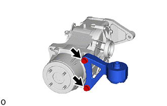
8. REMOVE REAR NO. 2 DIFFERENTIAL SUPPORT
(a) Remove the rear upper differential mount stopper from the rear No. 2 differential support.
| (b) Remove the 2 bolts and rear No. 2 differential support from the rear differential carrier assembly. |
|
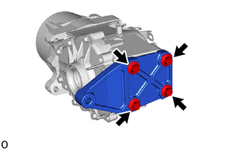
9. REMOVE REAR DIFFERENTIAL SUPPORT
| (a) Remove the 4 bolts and rear differential support from the rear differential carrier assembly. |
|
READ NEXT:
 Disassembly
DISASSEMBLY CAUTION / NOTICE / HINT
NOTICE: Before installation of each part, thoroughly clean and dry it. Then apply gear oil to it. Do not use alkaline chemicals to clean aluminum parts, rubber pa
Reassembly
REASSEMBLY CAUTION / NOTICE / HINT
NOTICE: Steps 10 to 17 are temporary reassembly procedures for adjustment purposes. PROCEDURE
1. INSTALL STRAIGHT PIN (a) Using a plastic-faced hammer, install t
Installation
INSTALLATION PROCEDURE 1. INSTALL REAR DIFFERENTIAL SUPPORT
(a) Install the rear differential support to the rear differential carrier assembly with 4 new bolts.
Torque: 72 N
SEE MORE:
Dtc Check / Clear
DTC CHECK / CLEAR CHECK DTC (a) Connect the GTS to the DLC3.
(b) Turn the ignition switch to ON. (c) Turn the intuitive parking assist system on.
(d) Turn the GTS on. (e) Enter the following menus: Body Electrical / Clearance Warning / Trouble Codes.
(f) Check for DTCs. Body Electrical > Cl
If the vehicle battery
is discharged
The following procedures may be used to start the engine if the
vehicle's battery is discharged.
You can also call your Toyota dealer or a qualified repair shop.
If you have a set of jumper (or booster) cables and a second vehicle
with a 12-volt battery, you can jump start your vehicle by foll
