Toyota Camry (XV70): Removal
REMOVAL
CAUTION / NOTICE / HINT
The necessary procedures (adjustment, calibration, initialization or registration) that must be performed after parts are removed and installed, or replaced during heated oxygen sensor removal/installation are shown below.
Necessary Procedures After Parts Removed/Installed/Replaced|
Replaced Part or Performed Procedure |
Necessary Procedure | Effect/Inoperative Function when Necessary Procedure not Performed |
Link |
|---|---|---|---|
| Inspection after repair |
|
|
PROCEDURE
1. REMOVE FRONT WHEEL OPENING EXTENSION PAD LH
Click here
.gif)
2. REMOVE FRONT WHEEL OPENING EXTENSION PAD RH
Click here
3. REMOVE NO. 1 ENGINE UNDER COVER
Click here
4. REMOVE REAR ENGINE UNDER COVER RH
Click here
5. REMOVE HEATED OXYGEN SENSOR (for Bank 1)
| (a) Disconnect the heated oxygen sensor connector. |
|
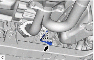
(b) Disengage the wire harness clamp.
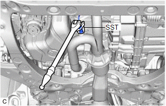
| (c) Using SST, remove the heated oxygen sensor from the front exhaust pipe assembly. SST: 09224-00012 NOTICE: If the heated oxygen sensor has been struck or dropped, replace it. |
|
6. REMOVE FRONT FLOOR COVER LH
Click here
7. REMOVE FRONT FLOOR COVER RH
Click here
8. REMOVE BODY MOUNTING PLATE
Click here
9. REMOVE NO. 1 EXHAUST PIPE SUPPORT BRACKET (for Lower Side)
Click here
10. REMOVE FRONT EXHAUST PIPE ASSEMBLY
Click here
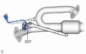
11. REMOVE HEATED OXYGEN SENSOR (for Bank 2)
| (a) Using SST, remove the heated oxygen sensor from the front exhaust pipe assembly. SST: 09224-00012 NOTICE: If the heated oxygen sensor has been struck or dropped, replace it. |
|
READ NEXT:
 Inspection
INSPECTION PROCEDURE 1. INSPECT HEATED OXYGEN SENSOR (for Bank 1)
(a) Measure the resistance according to the value(s) in the table below.
Standard Resistance:
Tester Connection Con
Installation
INSTALLATION PROCEDURE 1. INSTALL HEATED OXYGEN SENSOR (for Bank 2)
HINT: Perform "Inspection After Repair" after replacing the heated oxygen sensor.
Click here
(a) Using SST, install
SEE MORE:
On-vehicle Inspection
ON-VEHICLE INSPECTION CAUTION / NOTICE / HINT
HINT:
Water Pump Construction Evaporation Port and Drain Plug:
*1
Evaporation Port
*2
Mechanical Seal
*3
Fluid Catch Pocket
*4
Drain P
Lost Communication with Meter (B1324,B1325)
DESCRIPTION These DTCs are stored when communication between the radio and display receiver assembly and combination meter assembly or headup display (meter mirror sub-assembly)* is not possible.
DTC No. Detection Item
DTC Detection Condition Trouble Area
B1324 Lost Communic
