Toyota Camry (XV70): Removal
REMOVAL
CAUTION / NOTICE / HINT
The necessary procedures (adjustment, calibration, initialization or registration) that must be performed after parts are removed and installed, or replaced during knock control sensor removal/installation are shown below.
Necessary Procedures After Parts Removed/Installed/Replaced|
Replaced Part or Performed Procedure |
Necessary Procedure | Effect/Inoperative Function when Necessary Procedure not Performed |
Link |
|---|---|---|---|
|
Battery terminal is disconnected/reconnected |
Perform steering sensor zero point calibration |
Lane Tracing Assist System |
|
|
Pre-collision System | |||
|
Memorize steering angle neutral point |
Parking Assist Monitor System |
| |
|
Panoramic View Monitor System |
| ||
| Inspection after repair |
|
|
PROCEDURE
1. REMOVE FUEL DELIVERY PIPE
Click here
.gif)
2. REMOVE KNOCK CONTROL SENSOR
| (a) Disconnect the 2 knock control sensor connectors. |
|
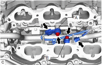
(b) Remove the 2 bolts and 2 knock control sensors from the cylinder block sub-assembly.
NOTICE:
If a knock control sensor has been struck or dropped, replace it.
READ NEXT:
 Inspection
INSPECTION PROCEDURE 1. INSPECT KNOCK CONTROL SENSOR
(a) Measure the resistance according to the value(s) in the table below.
Standard Resistance:
Tester Connection Condition
Installation
INSTALLATION PROCEDURE 1. INSTALL KNOCK CONTROL SENSOR
HINT: Perform "Inspection After Repair" after replacing a knock control sensor.
Click here
(a) Temporarily install the 2 knock contro
SEE MORE:
When the TRAC/VSC systems are operating - Driving assist systems
The slip indicator light will flash
while the TRAC/VSC systems are
operating.
Disabling the TRAC system
If the vehicle gets stuck in mud, dirt or snow, the TRAC system may
reduce power from the engine to the wheels. Pressing
to turn
the system off may make it easier for you to rock the vehi
Rear Brake Flexible Hose(w/ Electric Parking Brake System)
ComponentsCOMPONENTS ILLUSTRATION
*1 REAR FLEXIBLE HOSE
*2 GASKET
*3 UNION BOLT
*4 BRAKE LINE
Tightening torque for "Major areas involving basic vehicle performance such as moving/turning/stopping" : N*m (kgf*cm, ft.*lbf)
* For use with a
