Toyota Camry (XV70): Removal
REMOVAL
CAUTION / NOTICE / HINT
The necessary procedures (adjustment, calibration, initialization, or registration) that must be performed after parts are removed and installed, or replaced during engine unit removal/installation are shown below.
Necessary Procedure After Parts Removed/Installed/Replaced|
Replaced Part or Performed Procedure |
Necessary Procedure | Effect/Inoperative Function when Necessary Procedure not Performed |
Link |
|---|---|---|---|
| *1: When the ECM is replaced with a new one, reset memory is unnecessary. | |||
| Battery terminal is disconnected/reconnected |
Perform steering sensor zero point calibration |
Lane Tracing Assist System |
|
|
Pre-collision System | |||
|
Memorize steering angle neutral point |
Parking Assist Monitor System |
| |
|
Panoramic view monitor system |
| ||
|
Replacement of ECM | Vehicle Identification Number (VIN) registration |
MIL comes on |
|
|
ECU communication ID registration (Immobiliser system) |
Engine start function |
| |
| Inspection After Repair |
|
|
|
Replacement of automatic transaxle assembly |
|
|
|
|
Replacement of ECM (If possible, read the transaxle compensation code from the previous ECM) |
| ||
| Replacement of ECM (If impossible, read the transaxle compensation code from the previous ECM) |
| ||
| Replacement of ECM |
Code registration |
|
|
|
Replacement of automatic transaxle fluid |
ATF thermal degradation estimate reset |
The value of the Data List item "ATF Thermal Degradation Estimate" is not estimated correctly. |
|
|
Suspension, tires, etc. (The vehicle height changes because of suspension or tire replacement) |
Rear television camera assembly optical axis (Back camera position setting) |
Parking assist monitor system |
|
|
Replacement of front bumper assembly |
Front television camera view adjustment |
Panoramic view monitor system |
|
|
Suspension, tires, etc. (The vehicle height changes because of suspension or tire replacement) |
| ||
| Front wheel alignment adjustment |
|
|
|
PROCEDURE
1. REMOVE KNOCK CONTROL SENSOR
Click here
.gif)
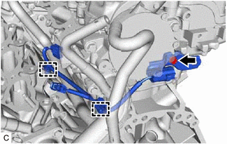
2. REMOVE SENSOR WIRE
| (a) Disengage the 2 clamps and remove the bolt and sensor wire. |
|
3. REMOVE IGNITION COIL ASSEMBLY
Click here
4. REMOVE VACUUM PUMP ASSEMBLY
Click here
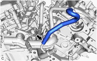
5. REMOVE NO. 3 WATER BY-PASS HOSE
| (a) Slide the clip and remove the No. 3 water by-pass hose from the water inlet pipe. |
|
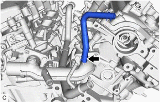
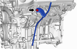
6. REMOVE NO. 2 WATER BY-PASS HOSE
| (a) Slide the clip and remove the No. 2 water by-pass hose from the water outlet. |
|
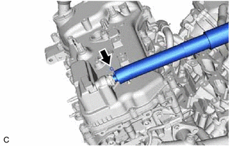
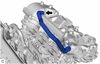
7. REMOVE VENTILATION HOSE
| (a) Slide the clip and remove the ventilation hose from the PCV valve (ventilation valve sub-assembly). |
|
8. REMOVE NO. 2 VENTILATION HOSE
| (a) Slide the clip and remove the No. 2 ventilation hose from the cylinder head cover sub-assembly. |
|
9. REMOVE V-RIBBED BELT
Click here
10. REMOVE GENERATOR ASSEMBLY
Click here
11. REMOVE COMPRESSOR ASSEMBLY WITH MAGNETIC CLUTCH
Click here
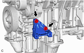
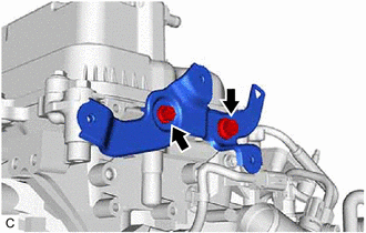
12. REMOVE NO. 1 COMPRESSOR MOUNTING BRACKET
| (a) Remove the 2 bolts and No. 1 compressor mounting bracket from the cylinder block sub-assembly. |
|
13. REMOVE NO. 2 IDLER PULLEY SUB-ASSEMBLY
Click here
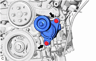
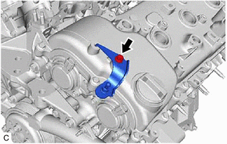
14. REMOVE V-RIBBED BELT TENSIONER ASSEMBLY
| (a) Remove the 2 bolts and V-ribbed belt tensioner assembly. |
|
15. REMOVE WATER PUMP PULLEY
Click here
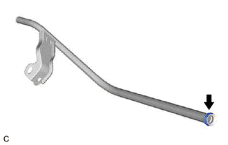
16. REMOVE ENGINE OIL LEVEL DIPSTICK GUIDE
(a) Remove the engine oil level dipstick from the engine oil level dipstick guide.
| (b) Remove the bolt and engine oil level dipstick guide from the camshaft housing sub-assembly LH and oil pan sub-assembly. |
|
| (c) Remove the engine oil level dipstick guide O-ring from the engine oil level dipstick guide. |
|
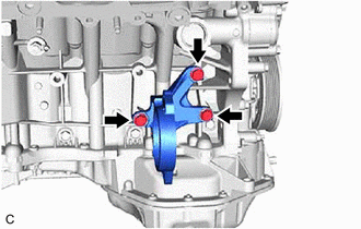
17. REMOVE DRIVE SHAFT BEARING BRACKET
| (a) Remove the 3 bolts and drive shaft bearing bracket from the cylinder block sub-assembly. |
|
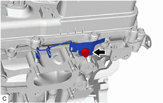
18. REMOVE WIRE HARNESS CLAMP BRACKET
| (a) Remove the bolt and wire harness clamp bracket from the camshaft housing sub-assembly LH. |
|
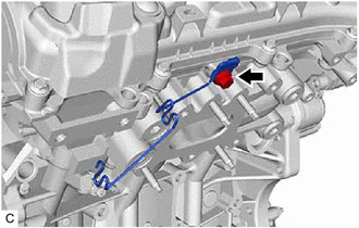
| (b) Remove the bolt and wire harness clamp bracket from the camshaft housing sub-assembly. |
|
19. REMOVE WATER FILLER BRACKET
| (a) Remove the 2 bolts and water filler bracket from the camshaft housing sub-assembly LH. |
|
20. REMOVE ENGINE COVER BRACKET
| (a) Remove the bolt and engine cover bracket from the cylinder head cover sub-assembly LH. |
|
READ NEXT:
 Disassembly
DISASSEMBLY PROCEDURE 1. REMOVE OIL FILLER CAP SUB-ASSEMBLY
(a) Remove the oil filler cap sub-assembly from the cylinder head cover sub-assembly LH.
(b) Remove the oil f
Inspection
INSPECTION PROCEDURE 1. INSPECT NO. 1 VALVE ROCKER ARM SUB-ASSEMBLY
(a) Turn the roller by hand to check that it turns smoothly. HINT:
If the roller does not turn smoothly, replace the No. 1
Reassembly
REASSEMBLY PROCEDURE 1. INSTALL CYLINDER BLOCK WATER JACKET SPACER
(a) Install the cylinder block water jacket spacer and cylinder block water jacket spacer LH to the cylinder block sub-assembly
SEE MORE:
Removal
REMOVAL CAUTION / NOTICE / HINT
The necessary procedures (adjustment, calibration, initialization or registration) that must be performed after parts are removed and installed, or replaced during knock control sensor removal/installation are shown below. Necessary Procedures After Parts Removed/In
Removal
REMOVAL CAUTION / NOTICE / HINT
HINT:
Use the same procedure for the RH side and LH side.
The following procedure is for the LH side.
PROCEDURE 1. REMOVE REAR WHEEL Click here
2. REMOVE REAR AXLE SHAFT NUT
(a) Using SST and a hammer, release the staked part of the rear axle s
