Toyota Camry (XV70): Removal
REMOVAL
CAUTION / NOTICE / HINT
The necessary procedures (adjustment, calibration, initialization, or registration) that must be performed after parts are removed and installed, or replaced during front crankshaft oil seal removal/installation are shown below.
Necessary Procedure After Parts Removed/Installed/Replaced|
Replaced Part or Performed Procedure |
Necessary Procedure | Effect/Inoperative Function when Necessary Procedure not Performed |
Link |
|---|---|---|---|
| *1: When the ECM is replaced with a new one, reset memory is unnecessary. | |||
| Battery terminal is disconnected/reconnected |
Perform steering sensor zero point calibration |
Lane Tracing Assist System |
|
|
Pre-collision System | |||
|
Memorize steering angle neutral point |
Parking Assist Monitor System |
| |
|
Panoramic view monitor system |
| ||
|
Replacement of ECM | Vehicle Identification Number (VIN) registration |
MIL comes on |
|
|
ECU communication ID registration (Immobiliser system) |
Engine start function |
| |
|
Gas leak from exhaust system is repaired |
Inspection After Repair |
|
|
|
Replacement of automatic transaxle assembly |
|
|
|
|
Replacement of ECM (If possible, read the transaxle compensation code from the previous ECM) |
| ||
| Replacement of ECM (If impossible, read the transaxle compensation code from the previous ECM) |
| ||
| Replacement of ECM |
Code registration |
|
|
|
Replacement of automatic transaxle fluid |
ATF thermal degradation estimate reset |
The value of the Data List item "ATF Thermal Degradation Estimate" is not estimated correctly. |
|
|
Suspension, tires, etc. (The vehicle height changes because of suspension or tire replacement) |
Rear television camera assembly optical axis (Back camera position setting) |
Parking assist monitor system |
|
|
Replacement of front bumper assembly |
Front television camera view adjustment |
Panoramic view monitor system |
|
|
Suspension, tires, etc. (The vehicle height changes because of suspension or tire replacement) |
| ||
| Front wheel alignment adjustment |
|
|
|
PROCEDURE
1. REMOVE ENGINE ASSEMBLY WITH TRANSAXLE
Click here
.gif)
2. REMOVE V-RIBBED BELT
Click here
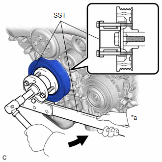
3. REMOVE CRANKSHAFT PULLEY
(a) Using SST to hold the crankshaft pulley, loosen the crankshaft pulley set bolt. Further loosen the crankshaft pulley set bolt until 2 or 3 threads remain screwed into the crankshaft.
|
*a | Hold |
.png) |
Turn |
SST: 09213-70011
09213-70020
SST: 09330-00021
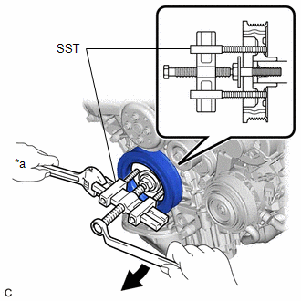
(b) Using SST, remove the crankshaft pulley set bolt and crankshaft pulley.
|
*a | Hold |
|
|
Turn |
SST: 09950-50013
09951-05010
09952-05010
09953-05020
09954-05021
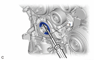
4. REMOVE TIMING CHAIN CASE OIL SEAL
| (a) Using a screwdriver with its tip wrapped with protective tape, pry out the timing chain case oil seal. NOTICE: After removal, check the crankshaft for damage. If it is damaged, smooth the surface with 400-grit sandpaper. |
|
READ NEXT:
 Installation
INSTALLATION PROCEDURE 1. INSTALL TIMING CHAIN CASE OIL SEAL
(a) Apply MP grease to the lip of a new timing chain case oil seal.
*a Oil Seal Protrusion Height
Components
COMPONENTS ILLUSTRATION
*1 REAR ENGINE OIL SEAL
*2 NO. 1 CRANKSHAFT POSITION SENSOR PLATE
*3 DRIVE PLATE AND RING GEAR SUB-ASSEMBLY
*4 REAR DRIVE PLATE SPACER
SEE MORE:
Removal
REMOVAL CAUTION / NOTICE / HINT
The necessary procedures (adjustment, calibration, initialization or registration) that must be performed after parts are removed and installed, or replaced during brake booster assembly removal/installation are shown below. Necessary Procedures After Parts Removed/
Zero Point Calibration of Steering Angle Sensor Initialization Malfunction (X208A)
DESCRIPTION
Code Tester Display
Measurement Item Trouble Area
X208A Zero Point Calibration of Steering Angle Sensor Initialization Malfunction
History of failure in acquiring steering angle zero point even after the vehicle is driven in a straight line at a vehicle spe
