Toyota Camry (XV70): Removal
REMOVAL
CAUTION / NOTICE / HINT
The necessary procedures (adjustment, calibration, initialization or registration) that must be performed after parts are removed and installed, or replaced during fuel injector assembly removal/installation are shown below.
Necessary Procedures After Parts Removed/Installed/Replaced|
Replaced Part or Performed Procedure |
Necessary Procedure | Effect/Inoperative Function when Necessary Procedure not Performed |
Link |
|---|---|---|---|
|
Battery terminal is disconnected/reconnected |
Perform steering sensor zero point calibration |
Lane Tracing Assist System |
|
|
Pre-collision System | |||
|
Memorize steering angle neutral point |
Parking Assist Monitor System |
| |
|
Panoramic View Monitor System |
| ||
| Inspection after repair |
|
|
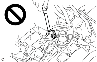
CAUTION:
- Never perform work on fuel system components near any possible ignition sources.
.png)
- Vaporized fuel could ignite, resulting in a serious accident.
- Do not perform work on fuel system components without first disconnecting the cable from the negative (-) battery terminal.
.png)
- Sparks could cause vaporized fuel to ignite, resulting in a serious accident.
- To prevent serious injury due to fuel spray from the high-pressure fuel lines, always discharge fuel system pressure before removing any fuel system components.
PROCEDURE
1. REMOVE FUEL (ENGINE ROOM SIDE) PUMP ASSEMBLY (for High Pressure)
Click here .gif)
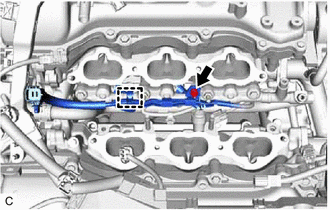
2. REMOVE NO. 2 FUEL PIPE SUB-ASSEMBLY
CAUTION:
To prevent serious injury due to fuel spray from the high-pressure fuel lines, always discharge fuel system pressure before removing any fuel system components.
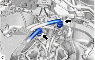
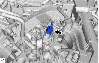
| (a) Using a 17 mm union nut wrench, loosen the 2 union nuts of the No. 2 fuel pipe sub-assembly. |
|
(b) Remove the No. 2 fuel pipe sub-assembly from the fuel delivery pipe with sensor assembly LH and fuel delivery pipe RH.
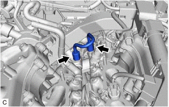
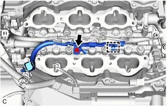
3. REMOVE WIRE HARNESS CLAMP BRACKET
| (a) Disconnect the No. 6 engine wire connector and No. 7 engine wire connector. |
|
| (b) Disengage the 2 clamps to remove the wire harness clamp bracket. |
|
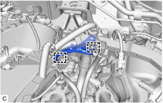
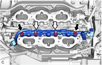
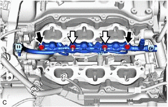
4. REMOVE FUEL DELIVERY PIPE WITH SENSOR ASSEMBLY LH
| (a) Disconnect the fuel pressure sensor connector. |
|
| (b) Remove the bolt. |
|
(c) Disengage the clamp to disconnect the No. 7 engine wire from the fuel delivery pipe with sensor assembly LH.
(d) Remove the 2 bolts, 2 nuts and fuel delivery pipe with sensor assembly LH with the 3 fuel injector assemblies from the cylinder head LH.
.png) |
Bolt |
.png) |
Nut |
NOTICE:
- If fuel intrudes into the combustion chamber, there may be adverse affects to the engine main body.
- Make sure not to touch or strike the tips of the fuel injector assemblies.
- Pull and remove the fuel delivery pipe with sensor assembly LH in a straight line without tilting it.
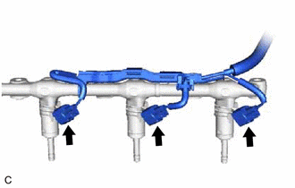
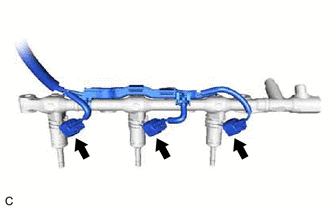
| (e) Disconnect the 3 fuel injector assembly connectors. |
|
5. REMOVE FUEL DELIVERY PIPE RH
| (a) Remove the bolt. |
|
(b) Disengage the clamp to disconnect the No. 6 engine wire from the fuel delivery pipe RH.
(c) Remove the 2 bolts, 2 nuts and fuel delivery pipe RH with the 3 fuel injector assemblies from the cylinder head sub-assembly.
|
|
Bolt |
|
|
Nut |
NOTICE:
- If fuel intrudes into the combustion chamber, there may be adverse affects to the engine main body.
- Make sure not to touch or strike the tips of the fuel injector assemblies.
- Pull and remove the fuel delivery pipe RH in a straight line without tilting it.
| (d) Disconnect the 3 fuel injector assembly connectors. |
|
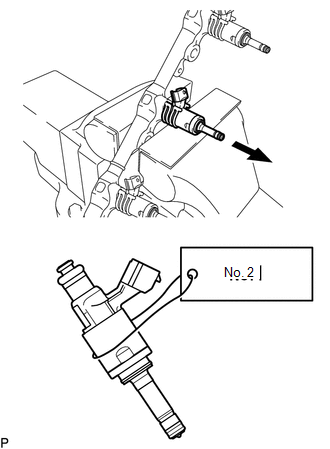
6. REMOVE FUEL INJECTOR ASSEMBLY
| (a) Secure the fuel delivery pipe with sensor assembly LH and fuel delivery pipe RH in a vise between aluminum plates and pull out the 6 fuel injector assemblies. NOTICE:
|
|
(b) Remove the nozzle holder clamp from each fuel injector assembly.
(c) Using needle nose pliers, remove the No. 3 fuel injector back-up ring from each fuel injector assembly.
NOTICE:
Do not damage the area that contacts the O-ring.
(d) Remove the O-ring and No. 1 fuel injector back-up ring from each fuel injector assembly.
(e) Remove the C-ring and injector vibration insulator from each fuel injector assembly.
7. REMOVE FUEL INJECTOR SEAL
| (a) Using the tip of needle nose pliers, pinch and pull the fuel injector seal at several points to stretch it. NOTICE:
|
|
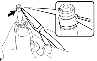
(b) Remove the fuel injector seal from each fuel injector assembly.
READ NEXT:
 Inspection
INSPECTION PROCEDURE 1. INSPECT FUEL INJECTOR ASSEMBLY
NOTICE: This inspection is for checking the fuel injector assembly for an open or short. Because the fuel injector assembly of this vehicle is
Installation
INSTALLATION PROCEDURE 1. INSTALL FUEL INJECTOR SEAL
(a) Apply engine conditioner to the area shown in the illustration. Using a piece of cloth, clean carbon deposits from the fuel injector asse
SEE MORE:
Right Rear Wheel Speed Sensor Internal Electronic Failure (C051249)
DESCRIPTION When the system is starting up and the skid control ECU (brake actuator assembly) detects a speed sensor circuit malfunction via the speed sensor circuit self-diagnosis function, this DTC is stored.
DTC No. Detection Item
DTC Detection Condition Trouble Area
C05124
Data List / Active Test
DATA LIST / ACTIVE TEST DATA LIST NOTICE:
In the table below, the values listed under "Normal Condition" are reference values. Do not depend solely on these reference values when deciding whether a part is faulty or not.
HINT: Using the Techstream to read the Data List allows the values or state
