Toyota Camry (XV70): Removal
REMOVAL
CAUTION / NOTICE / HINT
The necessary procedures (adjustment, calibration, initialization or registration) that must be performed after parts are removed and installed, or replaced during fuel sender gauge assembly removal/installation are shown below.
Necessary Procedures After Parts Removed/Installed/Replaced|
Replaced Part or Performed Procedure |
Necessary Procedure | Effect/Inoperative Function when Necessary Procedure not Performed |
Link |
|---|---|---|---|
|
Battery terminal is disconnected/reconnected |
Perform steering sensor zero point calibration. |
Lane Tracing Assist System |
|
|
Pre-collision System | |||
|
Memorize steering angle neutral point |
Parking Assist Monitor System |
| |
|
Panoramic View Monitor System |
|
CAUTION:
- Never perform work on fuel system components near any possible ignition sources.
.png)
- Vaporized fuel could ignite, resulting in a serious accident.
- Do not perform work on fuel system components without first disconnecting the cable from the negative (-) battery terminal.
.png)
- Sparks could cause vaporized fuel to ignite, resulting in a serious accident.
PROCEDURE
1. REMOVE FUEL SUCTION TUBE WITH PUMP AND GAUGE ASSEMBLY
Click here .gif)
2. REMOVE FUEL SENDER GAUGE ASSEMBLY
| (a) Disconnect the fuel sender gauge assembly connector. |
|

(b) Disengage the 2 clamps to disconnect the wire harness from the fuel suction plate sub-assembly.
NOTICE:
Do not damage the wire harness.
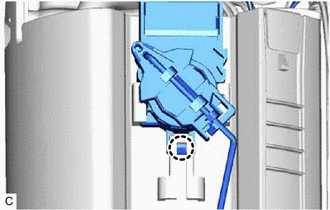
| (c) Disengage the claw to remove the fuel sender gauge assembly from the fuel suction tube with pump and gauge assembly. NOTICE: Be careful not to bend the arm of the fuel sender gauge assembly. |
|
READ NEXT:
 Inspection
INSPECTION PROCEDURE 1. INSPECT FUEL SENDER GAUGE ASSEMBLY
CAUTION: Perform the inspection in a well-ventilated area. Do not perform the inspection near an open flame.
(a) Check that the float mov
Installation
INSTALLATION PROCEDURE 1. INSTALL FUEL SENDER GAUGE ASSEMBLY
(a) Engage the claw to install the fuel sender gauge assembly to the fuel suction tube with pump and gauge assembly.
NOTICE: Be careful
Components
COMPONENTS ILLUSTRATION
*1 FUEL SENDER GAUGE ASSEMBLY
*2 FUEL SUCTION TUBE WITH PUMP AND GAUGE ASSEMBLY
SEE MORE:
Mute Signal Circuit between Radio Receiver and Stereo Component Amplifier
DESCRIPTION This circuit sends a signal to the stereo component amplifier assembly to mute noise. Because of that, the noise produced by changing the sound source ceases.
If there is an open in the circuit, noise can be heard from the speakers when changing the sound source.
If there is a short
Certification ECU Vehicle Information Reading/Writing Process Malfunction (B15F7)
DESCRIPTION This DTC is stored when items controlled by the certification ECU (smart key ECU assembly) cannot be customized via the audio and visual system vehicle customization screen.
HINT: The certification ECU (smart key ECU assembly) controls the smart key system related items that are custom
