Toyota Camry (XV70): Right Rear Wheel Speed Sensor Internal Electronic Failure (C051249)
DESCRIPTION
When the system is starting up and the skid control ECU (brake actuator assembly) detects a speed sensor circuit malfunction via the speed sensor circuit self-diagnosis function, this DTC is stored.
|
DTC No. | Detection Item |
DTC Detection Condition | Trouble Area |
|---|---|---|---|
|
C051249 | Right Rear Wheel Speed Sensor Internal Electronic Failure |
A circuit malfunction in the speed sensor is detected during the self test. |
|
*1: for 2WD
*2: for AWD
WIRING DIAGRAM
Refer to DTC C051212.
Click here
.gif)
CAUTION / NOTICE / HINT
NOTICE:
- After replacing the skid control ECU (brake actuator assembly), perform acceleration sensor zero point calibration and system information memorization.
Click here
- After replacing or removing and installing a speed sensor, perform Dealer Mode (Signal Check) inspection to confirm that the speed sensors are operating correctly.
Click here
PROCEDURE
|
1. | CHECK VEHICLE |
(a) Check the vehicle specification.
| Result |
Proceed to |
|---|---|
| for 2WD |
A |
| for AWD |
B |
| B |
.gif) | GO TO STEP 13 |
|
.gif)
| 2. |
CHECK HARNESS AND CONNECTOR (SENSOR CIRCUIT) |
| (a) Make sure that there is no looseness at the locking part and the connecting part of the connectors. OK: The connector is securely connected. |
|
.png)
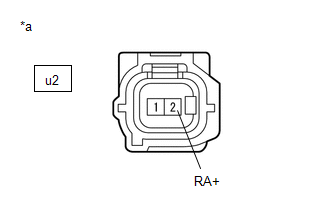
(b) Disconnect the u2 rear speed sensor RH (rear axle hub and bearing assembly RH) connector.
(c) Check both the connector case and the terminals for deformation and corrosion.
OK:
No deformation or corrosion.
(d) Turn the ignition switch to ON.
(e) Measure the voltage according to the value(s) in the table below.
Standard Voltage:
|
Tester Connection | Condition |
Specified Condition |
|---|---|---|
|
u2-2 (RA+) - u2-1 (RA-) |
Ignition switch on | 11 to 14 V |
| NG | | GO TO STEP 8 |
|
| 3. |
CHECK HARNESS AND CONNECTOR (SENSOR POWER SOURCE CIRCUIT) |
| (a) Make sure that there is no looseness at the locking part and the connecting part of the connectors. OK: The connector is securely connected. |
|
(b) Disconnect the u2 rear speed sensor RH (rear axle hub and bearing assembly RH) connector.
(c) Check both the connector case and the terminals for deformation and corrosion.
OK:
No deformation or corrosion.
(d) Measure the voltage according to the value(s) in the table below.
Standard Voltage:
|
Tester Connection | Condition |
Specified Condition |
|---|---|---|
|
u2-2 (RA+) - Body ground |
Ignition switch off | Below 1.5 V |
| NG | | GO TO STEP 6 |
|
| 4. |
INSPECT NO. 1 PARKING BRAKE WIRE ASSEMBLY |
| (a) Make sure that there is no looseness at the locking part and the connecting part of the connectors. OK: The connector is securely connected. |
|
.png)
(b) Disconnect the u2 skid control sensor wire RH (No. 1 parking brake wire assembly) connector.
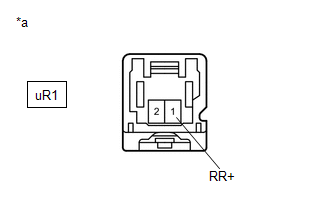
(c) Disconnect the uR1 skid control sensor wire RH (No. 1 parking brake wire assembly) connector.
(d) Check both the connector case and the terminals for deformation and corrosion.
OK:
No deformation or corrosion.
(e) Measure the resistance according to the value(s) in the table below.
Standard Resistance:
|
Tester Connection | Condition |
Specified Condition |
|---|---|---|
|
u2-1 (RA-) or uR1-2 (RR-) - Body ground and other terminals |
Always | 10 kΩ or higher |
| NG | | REPLACE NO. 1 PARKING BRAKE WIRE ASSEMBLY |
|
| 5. |
CHECK HARNESS AND CONNECTOR (NO. 1 PARKING BRAKE WIRE ASSEMBLY - BRAKE ACTUATOR ASSEMBLY) |
(a) Make sure that there is no looseness at the locking part and the connecting part of the connectors.
OK:
The connector is securely connected.
(b) Disconnect the A34 skid control ECU (brake actuator assembly) connector.
(c) Disconnect the uR1 skid control sensor wire RH (No. 1 parking brake wire assembly) connector.
(d) Check both the connector case and the terminals for deformation and corrosion.
OK:
No deformation or corrosion.
(e) Measure the resistance according to the value(s) in the table below.
Standard Resistance:
|
Tester Connection | Condition |
Specified Condition |
|---|---|---|
|
uR1-2 (RR-) or A34-37 (RR-) - Body ground |
Always | 10 kΩ or higher |
| OK | | REPLACE REAR AXLE HUB AND BEARING ASSEMBLY RH |
| NG | | REPAIR OR REPLACE HARNESS OR CONNECTOR |
| 6. |
CHECK HARNESS AND CONNECTOR (SENSOR POWER SOURCE CIRCUIT) |
| (a) Make sure that there is no looseness at the locking part and the connecting part of the connectors. OK: The connector is securely connected. |
|
(b) Disconnect the uR1 skid control sensor wire RH (No. 1 parking brake wire assembly) connector.
(c) Check both the connector case and the terminals for deformation and corrosion.
OK:
No deformation or corrosion.
(d) Measure the voltage according to the value(s) in the table below.
Standard Voltage:
|
Tester Connection | Condition |
Specified Condition |
|---|---|---|
|
uR1-1 (RR+) - Body ground |
Ignition switch off | Below 1.5 V |
| OK | | REPLACE NO. 1 PARKING BRAKE WIRE ASSEMBLY |
|
| 7. |
CHECK HARNESS AND CONNECTOR (NO. 1 PARKING BRAKE WIRE ASSEMBLY - BRAKE ACTUATOR ASSEMBLY) |
| (a) Make sure that there is no looseness at the locking part and the connecting part of the connectors. OK: The connector is securely connected. |
|
(b) Disconnect the A34 skid control ECU (brake actuator assembly) connector.
(c) Disconnect the uR1 skid control sensor wire RH (No.1 parking brake wire assembly) connector.
(d) Check both the connector case and the terminals for deformation and corrosion.
OK:
No deformation or corrosion.
(e) Measure the voltage according to the value(s) in the table below.
Standard Voltage:
|
Tester Connection | Condition |
Specified Condition |
|---|---|---|
|
uR1-1 (RR+) - Body ground |
Always | Below 1.5 V |
| OK | | REPLACE BRAKE ACTUATOR ASSEMBLY |
| NG | | REPAIR OR REPLACE HARNESS OR CONNECTOR |
| 8. |
CHECK HARNESS AND CONNECTOR (SENSOR CIRCUIT) |
| (a) Make sure that there is no looseness at the locking part and the connecting part of the connectors. OK: The connector is securely connected. |
|
.png)
(b) Disconnect the uR1 skid control sensor wire RH (No. 1 parking brake wire assembly) connector.
(c) Check both the connector case and the terminals for deformation and corrosion.
OK:
No deformation or corrosion.
(d) Turn the ignition switch to ON.
(e) Measure the voltage according to the value(s) in the table below.
Standard Voltage:
|
Tester Connection | Condition |
Specified Condition |
|---|---|---|
|
uR1-1 (RR+) - uR1-2 (RR-) |
Ignition switch on | 11 to 14 V |
| OK | | REPLACE NO. 1 PARKING BRAKE WIRE ASSEMBLY |
|
| 9. |
CHECK HARNESS AND CONNECTOR (SENSOR POWER SOURCE CIRCUIT) |
| (a) Make sure that there is no looseness at the locking part and the connecting part of the connectors. OK: The connector is securely connected. |
|
(b) Disconnect the uR1 skid control sensor wire RH (No. 1 parking brake wire assembly) connector.
(c) Check both the connector case and the terminals for deformation and corrosion.
OK:
No deformation or corrosion.
(d) Turn the ignition switch to ON.
(e) Measure the voltage according to the value(s) in the table below.
Standard Voltage:
|
Tester Connection | Condition |
Specified Condition |
|---|---|---|
|
uR1-1 (RR+) - Body ground |
Ignition switch on | 11 to 14 V |
| NG | | GO TO STEP 12 |
|
| 10. |
CHECK HARNESS AND CONNECTOR (NO. 1 PARKING BRAKE WIRE ASSEMBLY - BRAKE ACTUATOR ASSEMBLY) |
| (a) Make sure that there is no looseness at the locking part and the connecting part of the connectors. OK: The connector is securely connected. |
|
.png)
(b) Disconnect the A34 skid control ECU (brake actuator assembly) connector.
(c) Disconnect the uR1 skid control sensor wire RH (No. 1 parking brake wire assembly) connector.
(d) Check both the connector case and the terminals for deformation and corrosion.
OK:
No deformation or corrosion.
(e) Measure the voltage according to the value(s) in the table below.
Standard Voltage:
|
Tester Connection | Condition |
Specified Condition |
|---|---|---|
|
uR1-2 (RR-) - Body ground |
Always | Below 1.5 V |
| NG | | REPAIR OR REPLACE HARNESS OR CONNECTOR |
|
| 11. |
CHECK HARNESS AND CONNECTOR (NO. 1 PARKING BRAKE WIRE ASSEMBLY - BRAKE ACTUATOR ASSEMBLY) |
(a) Make sure that there is no looseness at the locking part and the connecting part of the connectors.
OK:
The connector is securely connected.
(b) Disconnect the A34 skid control ECU (brake actuator assembly) connector.
(c) Disconnect the uR1 skid control sensor wire RH (No. 1 parking brake wire assembly) connector.
(d) Check both the connector case and the terminals for deformation and corrosion.
OK:
No deformation or corrosion.
(e) Measure the resistance according to the value(s) in the table below.
Standard Resistance:
|
Tester Connection | Condition |
Specified Condition |
|---|---|---|
|
uR1-2 (RR-) - A34-37 (RR-) |
Always | Below 1 Ω |
|
uR1-1 (RR+) or A34-22 (RR+) - uR1-2 (RR-) or A34-37 (RR-) |
Always | 10 kΩ or higher |
| OK | | REPLACE BRAKE ACTUATOR ASSEMBLY |
| NG | | REPAIR OR REPLACE HARNESS OR CONNECTOR |
| 12. |
CHECK HARNESS AND CONNECTOR (NO. 1 PARKING BRAKE WIRE ASSEMBLY - BRAKE ACTUATOR ASSEMBLY) |
(a) Make sure that there is no looseness at the locking part and the connecting part of the connectors.
OK:
The connector is securely connected.
(b) Disconnect the A34 skid control ECU (brake actuator assembly) connector.
(c) Disconnect the uR1 skid control sensor wire RH (No. 1 parking brake wire assembly) connector.
(d) Check both the connector case and the terminals for deformation and corrosion.
OK:
No deformation or corrosion.
(e) Measure the resistance according to the value(s) in the table below.
Standard Resistance:
|
Tester Connection | Condition |
Specified Condition |
|---|---|---|
|
uR1-1 (RR+) - A34-22 (RR+) |
Always | Below 1 Ω |
|
uR1-1 (RR+) or A34-22 (RR+) - Body ground |
Always | 10 kΩ or higher |
| OK | | REPLACE BRAKE ACTUATOR ASSEMBLY |
| NG | | REPAIR OR REPLACE HARNESS OR CONNECTOR |
| 13. |
CHECK HARNESS AND CONNECTOR (SENSOR CIRCUIT) |
| (a) Make sure that there is no looseness at the locking part and the connecting part of the connectors. OK: The connector is securely connected. |
|
(b) Disconnect the u2 rear speed sensor RH connector.
(c) Check both the connector case and the terminals for deformation and corrosion.
OK:
No deformation or corrosion.
(d) Turn the ignition switch to ON.
(e) Measure the voltage according to the value(s) in the table below.
Standard Voltage:
|
Tester Connection | Condition |
Specified Condition |
|---|---|---|
|
u2-2 (RA+) - u2-1 (RA-) |
Ignition switch on | 11 to 14 V |
| NG | | GO TO STEP 8 |
|
| 14. |
CHECK HARNESS AND CONNECTOR (SENSOR POWER SOURCE CIRCUIT) |
| (a) Make sure that there is no looseness at the locking part and the connecting part of the connectors. OK: The connector is securely connected. |
|
(b) Disconnect the u2 rear speed sensor RH connector.
(c) Check both the connector case and the terminals for deformation and corrosion.
OK:
No deformation or corrosion.
(d) Measure the voltage according to the value(s) in the table below.
Standard Voltage:
|
Tester Connection | Condition |
Specified Condition |
|---|---|---|
|
u2-2 (RA+) - Body ground |
Ignition switch off | Below 1.5 V |
| NG | | GO TO STEP 6 |
|
| 15. |
INSPECT NO. 1 PARKING BRAKE WIRE ASSEMBLY |
| (a) Make sure that there is no looseness at the locking part and the connecting part of the connectors. OK: The connector is securely connected. |
|
(b) Disconnect the u2 skid control sensor wire RH (No. 1 parking brake wire assembly) connector.
(c) Disconnect the uR1 skid control sensor wire RH (No. 1 parking brake wire assembly) connector.
(d) Check both the connector case and the terminals for deformation and corrosion.
OK:
No deformation or corrosion.
(e) Measure the resistance according to the value(s) in the table below.
Standard Resistance:
|
Tester Connection | Condition |
Specified Condition |
|---|---|---|
|
u2-1 (RA-) or uR1-2 (RR-) - Body ground and other terminals |
Always | 10 kΩ or higher |
| NG | | REPLACE NO. 1 PARKING BRAKE WIRE ASSEMBLY |
|
| 16. |
CHECK HARNESS AND CONNECTOR (NO. 1 PARKING BRAKE WIRE ASSEMBLY - BRAKE ACTUATOR ASSEMBLY) |
(a) Make sure that there is no looseness at the locking part and the connecting part of the connectors.
OK:
The connector is securely connected.
(b) Disconnect the A34 skid control ECU (brake actuator assembly) connector.
(c) Disconnect the uR1 skid control sensor wire RH (No. 1 parking brake wire assembly) connector.
(d) Check both the connector case and the terminals for deformation and corrosion.
OK:
No deformation or corrosion.
(e) Measure the resistance according to the value(s) in the table below.
Standard Resistance:
|
Tester Connection | Condition |
Specified Condition |
|---|---|---|
|
uR1-2 (RR-) or A34-37 (RR-) - Body ground |
Always | 10 kΩ or higher |
| OK | | REPLACE REAR SPEED SENSOR RH |
| NG | | REPAIR OR REPLACE HARNESS OR CONNECTOR |
READ NEXT:
 Multi-axis Acceleration Sensor Module "A" Missing Calibration (C051D54)
DESCRIPTION The airbag sensor assembly has a built-in yaw rate and acceleration sensor and detects the vehicle condition.
The skid control ECU (brake actuator assembly) receives signals from the yaw
Multi-axis Acceleration Sensor Module "A" Circuit Voltage Out of Range (C05201C)
DESCRIPTION The airbag sensor assembly has a built-in yaw rate and acceleration sensor and detects the vehicle condition.
When the skid control ECU (brake actuator assembly) detects an abnormal acce
Multi-axis Acceleration Sensor Module "A" Circuit Voltage Out of Range (C05201C)
DESCRIPTION The airbag sensor assembly has a built-in yaw rate and acceleration sensor and detects the vehicle condition.
When the skid control ECU (brake actuator assembly) detects an abnormal acce
SEE MORE:
Parts Location
PARTS LOCATION ILLUSTRATION
*1 FRONT ENGINE MOUNTING INSULATOR
*2 REAR ENGINE MOUNTING INSULATOR
*3 CANISTER
*4 FUEL PUMP (for Low Pressure Side)
*5 MASS AIR FLOW METER SUB-ASSEMBLY
*6 PARK / NEUTRAL POSITION SWITCH ASSEMBLY
*7 VACUUM
Tire And Wheel
ComponentsCOMPONENTS ILLUSTRATION
*A for Steel Wheel
*B except Steel Wheel
*1 WHEEL ASSEMBLY
*2 AXLE HUB NUT
*3 WHEEL CAP
- -
Tightening torque for "Major areas involving basic vehicle performance such as moving/turning/stopping"
