Toyota Camry (XV70): Stop Lamp Relay Actuator Stuck On (C13807E)
DESCRIPTION
When any of the following conditions are met, the skid control ECU (brake actuator assembly) sets the drive output (STPO) ON which operates the stop light control relay (stop light switch assembly) and turns on the stop lights.
Illumination Conditions:- Pre-collision brake is operating.
- The dynamic radar cruise control system is operating and is applying the brakes.
- Secondary collision brake is operating.
|
DTC No. | Detection Item |
DTC Detection Condition | Trouble Area |
|---|---|---|---|
|
C13807E | Stop Lamp Relay Actuator Stuck On |
When the voltage at the +BS terminal is between 10 V or more and the stop light control relay (stop light switch assembly) drive output (STPO) is off, the signal at the STP2 terminal is different from the input signal at the STP terminal for 5 seconds or more. |
|
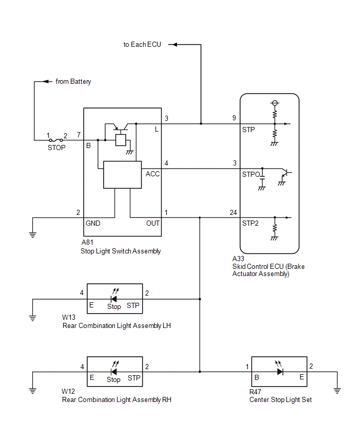
WIRING DIAGRAM
CAUTION / NOTICE / HINT
NOTICE:
- Inspect the fuses for circuits related to this system before performing the following procedure.
- After replacing the skid control ECU (brake actuator assembly), perform acceleration sensor zero point calibration and system information memorization.
Click here
.gif)
HINT:
When DTC P057111, P057112 and/or P057113 are output together with DTC C13807E, inspect and repair the trouble areas indicated by DTC P057111, P057112 and/or P057113 first.
P057111: Click here
P057112: Click here
P057113: Click here
PROCEDURE
| 1. |
CHECK STOP LIGHT ILLUMINATION STATUS |
(a) With the brake pedal released, check the illumination status of the brake lights.
|
Result | Proceed to |
|---|---|
|
The stop lights are illuminated. |
A |
| The stop lights are not illuminated. |
B |
| B |
.gif) | GO TO STEP 7 |
|
.gif)
| 2. |
CHECK HARNESS AND CONNECTOR (STOP LIGHT CONTROL RELAY CIRCUIT) |
| (a) Make sure that there is no looseness at the locking part and the connecting part of the connector. OK: The connector is securely connected. |
|
(b) Measure the voltage according to the value(s) in the table below.
Standard Voltage:
|
Tester Connection | Condition |
Specified Condition |
|---|---|---|
|
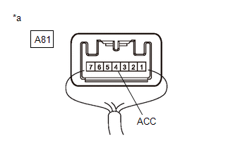
A81-4 (ACC) - Body ground |
Always | 11 to 14 V |
| NG | | GO TO STEP 5 |
|
| 3. |
CHECK STOP LIGHT ILLUMINATION STATUS |
(a) Make sure that there is no looseness at the locking part and the connecting part of the connector.
OK:
The connector is securely connected.
(b) Disconnect the A81 stop light switch assembly connector.
(c) Check both the connector case and the terminals for deformation and corrosion.
OK:
No deformation or corrosion.
(d) Check the illumination status of the brake lights.
|
Result | Proceed to |
|---|---|
|
The stop lights are illuminated. |
A |
| The stop lights are not illuminated. |
B |
| B |
| REPLACE STOP LIGHT SWITCH ASSEMBLY |
|
| 4. |
CHECK STOP LIGHT ILLUMINATION STATUS |
(a) Make sure that there is no looseness at the locking part and the connecting part of the connector.
OK:
The connector is securely connected.
(b) Disconnect the A33 skid control ECU (brake actuator assembly) connector.
(c) Disconnect the A81 stop light switch assembly connector.
(d) Check both the connector case and the terminals for deformation and corrosion.
OK:
No deformation or corrosion.
(e) Check the illumination status of the brake lights.
|
Result | Proceed to |
|---|---|
|
The stop lights are illuminated. |
A |
| The stop lights are not illuminated. |
B |
| A |
| REPAIR OR REPLACE HARNESS OR CONNECTOR (STOP LIGHT CIRCUIT) |
| B |
| REPLACE BRAKE ACTUATOR ASSEMBLY |
| 5. |
CHECK HARNESS AND CONNECTOR (STOP LIGHT CONTROL RELAY CIRCUIT) |
| (a) Make sure that there is no looseness at the locking part and the connecting part of the connectors. OK: The connector is securely connected. |
|
(b) Disconnect the A33 skid control ECU (brake actuator assembly) connector.
(c) Check both the connector case and the terminals for deformation and corrosion.
OK:
No deformation or corrosion.
(d) Measure the voltage according to the value(s) in the table below.
Standard Voltage:
|
Tester Connection | Condition |
Specified Condition |
|---|---|---|
|
A81-4 (ACC) - Body ground |
Always | 11 to 14 V |
| OK | | REPLACE BRAKE ACTUATOR ASSEMBLY |
|
| 6. |
CHECK HARNESS AND CONNECTOR (STOP LIGHT SWITCH ASSEMBLY - BRAKE ACTUATOR ASSEMBLY) |
(a) Make sure that there is no looseness at the locking part and the connecting part of the connectors.
OK:
The connector is securely connected.
(b) Disconnect the A81 stop right switch assembly connector.
(c) Disconnect the A33 skid control ECU (brake actuator assembly) connector.
(d) Check both the connector case and the terminals for deformation and corrosion.
OK:
No deformation or corrosion.
(e) Measure the resistance according to the value(s) in the table below.
Standard Resistance:
|
Tester Connection | Condition |
Specified Condition |
|---|---|---|
|
A81-4 (ACC) or A33-3 (STPO) - Body ground and other terminals |
Always | 10 kΩ or higher |
| OK | | REPLACE STOP LIGHT SWITCH ASSEMBLY |
| NG | | REPAIR OR REPLACE HARNESS OR CONNECTOR |
| 7. |
CHECK STOP LIGHT OPERATION |
(a) Check that the stop lights come on when the brake pedal is depressed.
OK:
The stop lights illuminate.
| NG | | GO TO STEP 9 |
|
| 8. |
CHECK HARNESS AND CONNECTOR (STOP LIGHT SIGNAL INPUT CIRCUIT) |
| (a) Make sure that there is no looseness at the locking part and the connecting part of the connectors. OK: The connector is securely connected. |
|
(b) Disconnect the A33 skid control ECU (brake actuator assembly) connector.
(c) Check both the connector case and the terminals for deformation and corrosion.
OK:
No deformation or corrosion.
(d) Measure the voltage according to the value(s) in the table below.
Standard Voltage:
|
Tester Connection | Condition |
Specified Condition |
|---|---|---|
|
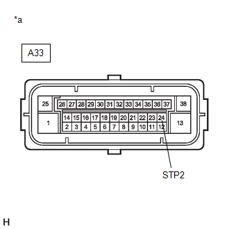
A33-24 (STP2) - Body ground |
Brake pedal depressed |
11 to 14 V |
| OK | | REPLACE BRAKE ACTUATOR ASSEMBLY |
| NG | | REPAIR OR REPLACE HARNESS OR CONNECTOR |
| 9. |
CHECK STOP LIGHT OPERATION |
(a) Make sure that there is no looseness at the locking part and the connecting part of the connectors.
OK:
The connector is securely connected.
(b) Disconnect the A33 skid control ECU (brake actuator assembly) connector.
(c) Check both the connector case and the terminals for deformation and corrosion.
OK:
No deformation or corrosion.
(d) Check that the stop lights come on when the brake pedal is depressed.
OK:
The stop lights illuminate.
| OK | | REPLACE BRAKE ACTUATOR ASSEMBLY |
|
| 10. |
CHECK HARNESS AND CONNECTOR (STOP LIGHT SWITCH ASSEMBLY - REAR COMBINATION LIGHT ASSEMBLY LH) |
| (a) Make sure that there is no looseness at the locking part and the connecting part of the connectors. OK: The connector is securely connected. |
|
(b) Disconnect the A33 skid control ECU (brake actuator assembly) connector.
(c) Disconnect the W13 rear combination light assembly LH connector.
(d) Check both the connector case and the terminals for deformation and corrosion.
OK:
No deformation or corrosion.
(e) Measure the voltage according to the value(s) in the table below.
Standard Voltage:
|
Tester Connection | Condition |
Specified Condition |
|---|---|---|
|
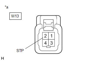
W13-2 (STP) - Body ground |
Brake pedal depressed |
11 to 14 V |
| OK | | GO TO LIGHTING SYSTEM (REAR COMBINATION LIGHT ASSEMBLY LH (STOP LIGHT CIRCUIT)) Refer to "Left or right stop light does not illuminate" of problem symptoms table. Click here |
|
| 11. |
CHECK HARNESS AND CONNECTOR (STOP LIGHT SWITCH ASSEMBLY - REAR COMBINATION LIGHT ASSEMBLY RH) |
| (a) Make sure that there is no looseness at the locking part and the connecting part of the connectors. OK: The connector is securely connected. |
|
(b) Disconnect the A33 skid control ECU (brake actuator assembly) connector.
(c) Disconnect the W13 rear combination light assembly LH connector.
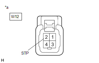
(d) Disconnect the W12 rear combination light assembly RH connector.
(e) Check both the connector case and the terminals for deformation and corrosion.
OK:
No deformation or corrosion.
(f) Measure the voltage according to the value(s) in the table below.
Standard Voltage:
|
Tester Connection | Condition |
Specified Condition |
|---|---|---|
|
W12-2 (STP) - Body ground |
Brake pedal depressed |
11 to 14 V |
| OK | | GO TO LIGHTING SYSTEM (REAR COMBINATION LIGHT ASSEMBLY RH (STOP LIGHT CIRCUIT)) Refer to "Left or right stop light does not illuminate" of problem symptoms table. Click here |
|
| 12. |
CHECK HARNESS AND CONNECTOR (STOP LIGHT SWITCH ASSEMBLY - CENTER STOP LIGHT SET) |
| (a) Make sure that there is no looseness at the locking part and the connecting part of the connectors. OK: The connector is securely connected. |
|
(b) Disconnect the A33 skid control ECU (brake actuator assembly) connector.
(c) Disconnect the W13 rear combination light assembly LH connector.
(d) Disconnect the W12 rear combination light assembly RH connector.
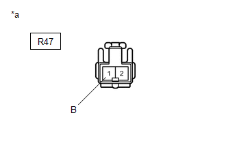
(e) Disconnect the R47 center stop light set connector.
(f) Check both the connector case and the terminals for deformation and corrosion.
OK:
No deformation or corrosion.
(g) Measure the voltage according to the value(s) in the table below.
Standard Voltage:
|
Tester Connection | Condition |
Specified Condition |
|---|---|---|
|
R47-1 (B) - Body ground |
Brake pedal depressed |
11 to 14 V |
| OK | | REPLACE CENTER STOP LIGHT SET |
|
| 13. |
CHECK HARNESS AND CONNECTOR (STOP LIGHT SWITCH ASSEMBLY - REAR COMBINATION LIGHT ASSEMBLY LH) |
(a) Make sure that there is no looseness at the locking part and the connecting part of the connectors.
OK:
The connector is securely connected.
(b) Disconnect the A33 skid control ECU (brake actuator assembly) connector.
(c) Disconnect the W13 rear combination light assembly LH connector.
(d) Disconnect the W12 rear combination light assembly RH connector.
(e) Disconnect the R47 center stop light set connector.
(f) Disconnect the A81 stop light switch assembly connector.
(g) Check both the connector case and the terminals for deformation and corrosion.
OK:
No deformation or corrosion.
(h) Measure the resistance according to the value(s) in the table below.
Standard Resistance:
|
Tester Connection | Condition |
Specified Condition |
|---|---|---|
|
A81-1 (OUT) - W13-2 (STP) |
Always | Below 1 Ω |
|
A81-1 (OUT) or W13-2 (STP) - Body ground |
Always | 10 kΩ or higher |
| OK | | REPLACE STOP LIGHT SWITCH ASSEMBLY |
| NG | | REPAIR OR REPLACE HARNESS OR CONNECTOR |
READ NEXT:
 Stop Lamp Relay Actuator Stuck Off (C13807F)
DESCRIPTION Refer to DTC C13807E. Click here
DTC No. Detection Item
DTC Detection Condition Trouble Area
C13807F Stop Lamp Relay Actuator Stuck Off
When the voltage
Brake Pressure Control Solenoid "A" Control Circuit Short to Battery (C13C012,...,C13C949)
DESCRIPTION The ABS solenoid relay and master cylinder cut solenoid valves are built into the brake actuator assembly.
Depending on the operating conditions, the master cylinder cut solenoid valves
ABS Solenoid Control Module Actuator Stuck On (C143A7E,C143A7F,C143D49,C14DA14)
DESCRIPTION The ABS solenoid relay is built into the skid control ECU in the brake actuator assembly. The ABS solenoid relay supplies power to each solenoid.
The skid control ECU (brake actuator ass
SEE MORE:
Reassembly
REASSEMBLY CAUTION / NOTICE / HINT
NOTICE:
When using a vise, place aluminum plates between the part and vise.
When using a vise, do not overtighten it.
HINT:
Use the same procedure for the RH and LH sides.
The procedure listed below is for the LH side.
PROCEDURE 1. INSTAL
Parking brake
Operating instructions
To set the parking brake, fully
depress the parking brake pedal
with your left foot while depressing
the brake pedal with your right
foot.
(Depressing the pedal again
releases the parking brake.)
■Parking brake engaged warning buzzer
A buzzer will sound if the v
