Toyota Camry (XV70): System Diagram
Toyota Camry Repair Manual XV70 (2018-2024) / Engine, Hybrid System / 2gr-fks (engine Control) / Ignition System / System Diagram
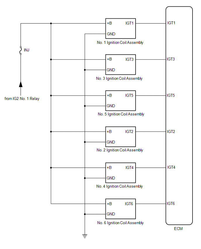
SYSTEM DIAGRAM
READ NEXT:
 On-vehicle Inspection
ON-VEHICLE INSPECTION CAUTION / NOTICE / HINT
CAUTION: To prevent injury due to contact with an operating V-ribbed belt or cooling fan, keep your hands and clothing away from the V-ribbed belt and c
Components
COMPONENTS ILLUSTRATION
*1 KNOCK CONTROL SENSOR (for Bank 1)
*2 KNOCK CONTROL SENSOR (for Bank 2)
N*m (kgf*cm, ft.*lbf): Specified torque
* For use with a un
SEE MORE:
Reassembly
REASSEMBLY PROCEDURE 1. INSTALL FRONT DIFFERENTIAL CASE FRONT TAPERED ROLLER BEARING (INNER RACE)
(a) Using SST and a press, install a new front differential case front tapered roller bearing (inner race) to the differential case assembly.
SST: 09316-20011 SST: 09950-60021 09951-00890 SST:
Utility
UTILITY INITIALIZE THE CONNECTION INFORMATION OF A GATEWAY FUNCTION EQUIPPED ECU (BUS MONITOR ECU)
(a) Connect the Techstream to the DLC3. (b) Turn the ignition switch to ON.
(c) Turn the Techstream on. (d) Enter the following menus:
for Body Electrical / Central Gateway / Utility / Initial
© 2023-2026 Copyright www.tocamry.com
