Toyota Camry (XV70): Components
COMPONENTS
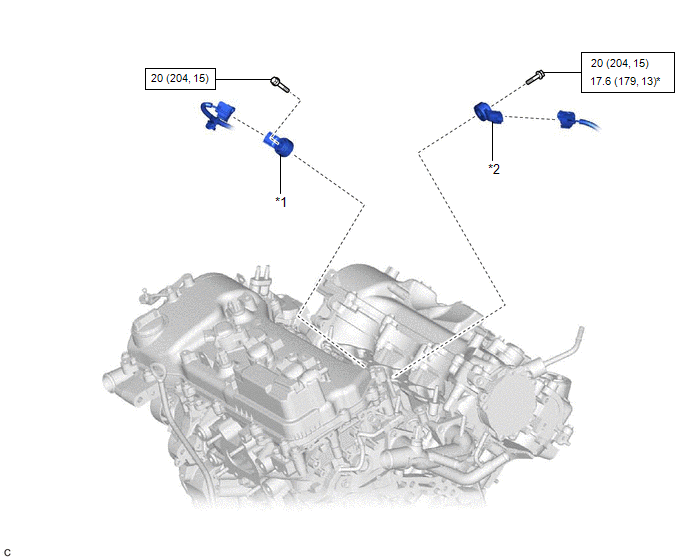
ILLUSTRATION
|
*1 | KNOCK CONTROL SENSOR (for Bank 1) |
*2 | KNOCK CONTROL SENSOR (for Bank 2) |
.png) |
N*m (kgf*cm, ft.*lbf): Specified torque |
* | For use with a union nut wrench |
READ NEXT:
 Removal
REMOVAL CAUTION / NOTICE / HINT
The necessary procedures (adjustment, calibration, initialization or registration) that must be performed after parts are removed and installed, or replaced during kn
Inspection
INSPECTION PROCEDURE 1. INSPECT KNOCK CONTROL SENSOR
(a) Measure the resistance according to the value(s) in the table below.
Standard Resistance:
Tester Connection Condition
Installation
INSTALLATION PROCEDURE 1. INSTALL KNOCK CONTROL SENSOR
HINT: Perform "Inspection After Repair" after replacing a knock control sensor.
Click here
(a) Temporarily install the 2 knock contro
SEE MORE:
Inspection
INSPECTION PROCEDURE 1. INSPECT REAR SPEAKER ASSEMBLY (for 6 Speakers)
(a) With the speaker installed, check that there is no looseness or other abnormalities.
(b) Check that there is no foreign matter in the speaker, no tears on the speaker cone or other abnormalities.
(c) Measure the res
On-vehicle Inspection
ON-VEHICLE INSPECTION PROCEDURE
1. FUEL PUMP ASSEMBLY OPERATION (a) Check fuel pressure. (1) Connect the Techstream to the DLC3.
(2) Start the engine. (3) Turn the Techstream on. (4) Enter the following menus: Powertrain / Engine / Active Test / Control the Target Fuel Pressure Offset. Powertrai
© 2023-2025 Copyright www.tocamry.com
