Toyota Camry (XV70): Telephone And Gps Antenna (for Front Side)
Components
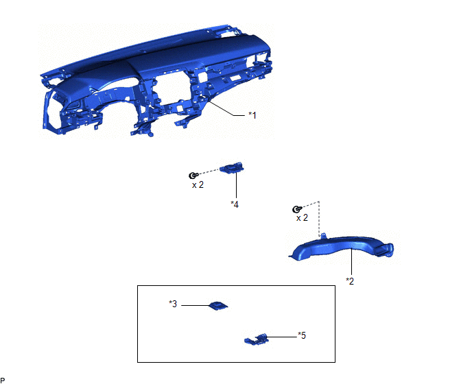
COMPONENTS
ILLUSTRATION
|
*1 | INSTRUMENT PANEL SAFETY PAD SUB-ASSEMBLY |
*2 | NO. 3 HEATER TO REGISTER DUCT SUB-ASSEMBLY |
|
*3 | TELEPHONE AND GPS ANTENNA ASSEMBLY |
*4 | TELEPHONE AND GPS ANTENNA ASSEMBLY WITH BRACKET |
|
*5 | TELEPHONE AND GPS ANTENNA BRACKET |
- | - |
Removal
REMOVAL
CAUTION / NOTICE / HINT
The necessary procedures (adjustment, calibration, initialization, or registration) that must be performed after parts are removed and installed, or replaced during telephone and GPS antenna assembly removal/installation are shown below.
Necessary Procedures After Parts Removed/Installed/Replaced|
Replaced Part or Performed Procedure |
Necessary Procedure | Effect/Inoperative Function when Necessary Procedure not Performed |
Link |
|---|---|---|---|
|
Disconnect cable from negative battery terminal |
Perform steering sensor zero point calibration. |
Lane Tracing Assist System |
|
|
Pre-collision System | |||
|
Memorize steering angle neutral point |
Parking Assist Monitor System |
| |
|
Panoramic View Monitor System |
|
CAUTION:
Some of these service operations affect the SRS airbag system. Read the precautionary notices concerning the SRS airbag system before servicing.
Click here
.gif)
PROCEDURE
1. REMOVE INSTRUMENT PANEL SAFETY PAD SUB-ASSEMBLY
Click here
2. REMOVE NO. 3 HEATER TO REGISTER DUCT SUB-ASSEMBLY
Click here
3. REMOVE TELEPHONE AND GPS ANTENNA ASSEMBLY WITH BRACKET
| (a) Disconnect the connector. |
|
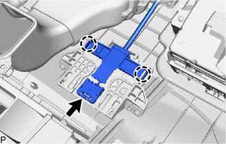
(b) Disengage the 2 claws.
| (c) Remove the 2 screws and telephone and GPS antenna assembly with bracket. |
|
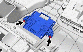
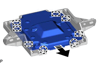
4. REMOVE TELEPHONE AND GPS ANTENNA ASSEMBLY
(a) Disengage the 2 claws and 6 guides to remove the telephone and GPS antenna assembly as shown in the illustration.
.png) |
Remove in this Direction |
5. REMOVE TELEPHONE AND GPS ANTENNA BRACKET
Installation
INSTALLATION
PROCEDURE
1. INSTALL TELEPHONE AND GPS ANTENNA BRACKET
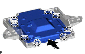
2. INSTALL TELEPHONE AND GPS ANTENNA ASSEMBLY
(a) Engage the 6 guides and 2 claws to install the telephone and GPS antenna assembly as shown in the illustration.
.png) |
Install in this Direction |
3. INSTALL TELEPHONE AND GPS ANTENNA ASSEMBLY WITH BRACKET
(a) Install the telephone and GPS antenna assembly with bracket with the 2 screws.
(b) Engage the 2 claws.
(c) Connect the connector.
4. INSTALL NO. 3 HEATER TO REGISTER DUCT SUB-ASSEMBLY
Click here .gif)
5. INSTALL INSTRUMENT PANEL SAFETY PAD SUB-ASSEMBLY
Click here
READ NEXT:
 Components
COMPONENTS ILLUSTRATION
*A except Panoramic Moon Roof
- -
*1 TELEPHONE AND GPS ANTENNA ASSEMBLY
*2 TELEPHONE AND GPS ANTENNA ASSEMBLY WITH COVER
*3 COVE
Removal
REMOVAL CAUTION / NOTICE / HINT
The necessary procedures (adjustment, calibration, initialization, or registration) that must be performed after parts are removed and installed, or replaced during t
SEE MORE:
Noise Occurs
PROCEDURE
1. CHECK NOISE CONDITION
(a) Check from which direction the noise comes (front left or right, or rear left or right).
OK: The location of the noise source can be determined.
NG
GO TO STEP 3
OK
2.
CHECK SPEAKERS (a
Initialization
INITIALIZATION
Necessary Procedure Effect/Inoperative Function when Necessary Procedure not Performed
Link Perform steering sensor zero point calibration
Lane Tracing Assist System
Pre-collision System
Memorize steering angle neutral point
Parkin
