Toyota Camry (XV70): VSC OFF Switch Circuit
DESCRIPTION
The skid control ECU (brake actuator assembly) is connected to the combination meter assembly via CAN communication.
Pressing the VSC OFF switch turns off TRAC operation, and pressing and holding this switch turns off TRAC and VSC operation. If TRAC and VSC operations are turned off, "Traction Control Turned Off" will be displayed on the multi-information display and the VSC OFF indicator light will come on.
WIRING DIAGRAM
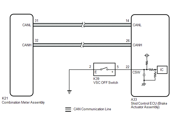
CAUTION / NOTICE / HINT
NOTICE:
After replacing the skid control ECU (brake actuator assembly), perform acceleration sensor zero point calibration and system information memorization.
Click here .gif)
PROCEDURE
| 1. |
READ VALUE USING TECHSTREAM (TRAC/VSC OFF MODE) |
(a) Connect the Techstream to the DLC3.
(b) Turn the ignition switch to ON.
(c) Enter the following menus: Chassis / Brake / Data List.
Chassis > Brake > Data List|
Tester Display | Measurement Item |
Range | Normal Condition |
Diagnostic Note |
|---|---|---|---|---|
|
TRC(TRAC)/VSC OFF Mode |
TRAC/VSC off mode | Normal mode (TRC(TRAC) ON/VSC ON) / TRC(TRAC) OFF mode (TRC(TRAC) OFF/VSC ON) / VSC expert mode (VSC expert mode MID ON) / VSC OFF mode (TRC(TRAC) OFF/VSC OFF) |
Normal mode (TRC(TRAC) ON/VSC ON): Normal mode TRC(TRAC) OFF mode (TRC(TRAC) OFF/VSC ON): TRAC off mode VSC expert mode (VSC expert mode MID ON): VSC expert mode VSC OFF mode (TRC(TRAC) OFF/VSC OFF): VSC off mode |
- |
|
Tester Display |
|---|
| TRC(TRAC)/VSC OFF Mode |
(d) Check the indicator light and mode condition on the Techstream changes according to VSC OFF switch operation.
Standard:
|
Switch Operation | Mode Condition Display |
Multi-information Display ("Traction Control Turned Off") |
VSC OFF Indicator Light |
|---|---|---|---|
|
Not pressed | Normal mode (TRC(TRAC) ON/VSC ON) |
Not displayed | Does not come on |
|
Pressing the VSC OFF switch |
TRC(TRAC) OFF mode (TRC(TRAC) OFF/VSC ON) |
Displayed | Does not come on |
|
Pressing and holding the VSC OFF switch |
VSC OFF mode (TRC(TRAC) OFF/VSC OFF) |
Displayed | Comes on |
|
Result | Proceed to |
|---|---|
|
Indicator light and mode condition display do not change |
A |
| Mode condition display is normal, but indicator light does not change |
B |
| Indicator light and mode condition display are normal |
C |
| B |
.gif) | INSPECT METER / GAUGE SYSTEM |
| C |
| USE SIMULATION METHOD TO CHECK
|
|
.gif)
| 2. |
INSPECT VSC OFF SWITCH |
(a) Inspect the VSC OFF Switch.
Click here
OK:
VSC OFF Switch is normal.
| NG | | REPLACE VSC OFF SWITCH |
|
| 3. |
CHECK HARNESS AND CONNECTOR (BRAKE ACTUATOR ASSEMBLY - VSC OFF SWITCH) |
(a) Make sure that there is no looseness at the locking part and the connecting part of the connector.
OK:
The connector is securely connected.
(b) Disconnect the A33 skid control ECU (brake actuator assembly) connector.
(c) Disconnect the K39 VSC OFF switch connector.
(d) Check both the connector case and the terminals for deformation and corrosion.
OK:
No deformation or corrosion.
(e) Measure the resistance according to the value(s) in the table below.
Standard Resistance:
|
Tester Connection | Condition |
Specified Condition |
|---|---|---|
|
K39-5 (+) - A33-22 (CSW) |
Always | Below 1 Ω |
|
K39-5 (+) or A33-22 (CSW) - Body ground |
Always | 10 kΩ or higher |
|
K39-2 (E) - Body ground |
1 minute or more after disconnecting the cable from the negative (-) battery terminal |
Below 1 Ω |
| OK | | REPLACE BRAKE ACTUATOR ASSEMBLY |
| NG | | REPAIR OR REPLACE HARNESS OR CONNECTOR |
READ NEXT:
 Components
COMPONENTS ILLUSTRATION
*1 COWL SIDE TRIM SUB-ASSEMBLY LH
*2 FRONT DOOR OPENING TRIM WEATHERSTRIP LH
*3 FRONT DOOR SCUFF PLATE LH
*4 HOOD LOCK CONTROL LEVER SUB-A
Removal
REMOVAL PROCEDURE 1. REMOVE FRONT DOOR SCUFF PLATE LH
Click here
2. REMOVE COWL SIDE TRIM SUB-ASSEMBLY LH Click here
3. REMOVE NO. 1 INSTRUMENT PANEL UNDER COVER SUB-
SEE MORE:
DCM Data Signal Circuit between Navigation ECU and DCM
DESCRIPTION This circuit is used to send and receive signals between the DCM (Telematics Transceiver) and radio and display receiver assembly or navigation ECU. WIRING DIAGRAM
PROCEDURE
1.
CHECK HARNESS AND CONNECTOR (RADIO AND DISPLAY RECEIVER ASSEMBLY - DCM (TELEMATICS TRANSCEIVER))
Replacement
REPLACEMENT PROCEDURE 1. REPLACE STRAIGHT PIN
NOTICE: If a straight pin is deformed, replace it. (a) Using a plastic hammer, tap in new straight pins to the cylinder block sub-assembly.
*a Front Side
*b Rear Side
*c Top Side
*d Bottom Side
*e RH Side
