Toyota Camry (XV70): Components
COMPONENTS
ILLUSTRATION
|
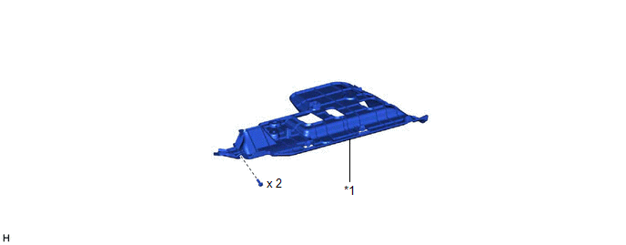
*1 | NO. 1 INSTRUMENT PANEL UNDER COVER SUB-ASSEMBLY |
- | - |
ILLUSTRATION
.png)
|
*1 | FRONT CENTER UPPER SUSPENSION BRACE SUB-ASSEMBLY |
- | - |
.png) |
Tightening torque for "Major areas involving basic vehicle performance such as moving/turning/stopping" : N*m (kgf*cm, ft.*lbf) |
.png) |
N*m (kgf*cm, ft.*lbf): Specified torque |
ILLUSTRATION
|
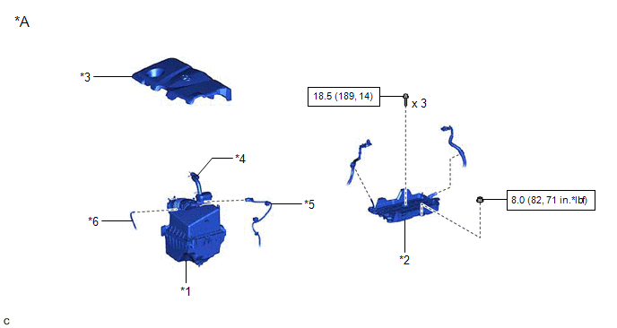
*A | for A25A-FKS |
- | - |
|
*1 | AIR CLEANER ASSEMBLY WITH AIR CLEANER HOSE |
*2 | BATTERY CLAMP SUB-ASSEMBLY |
|
*3 | NO. 1 ENGINE COVER SUB-ASSEMBLY |
*4 | NO. 2 VENTILATION HOSE |
|
*5 | MASS AIR FLOW METER SUB-ASSEMBLY CONNECTOR |
*6 | VACUUM HOSE |
|
|
N*m (kgf*cm, ft.*lbf): Specified torque |
- | - |
ILLUSTRATION
|
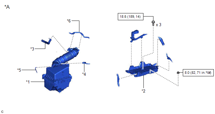
*A | for 2GR-FKS |
- | - |
|
*1 | AIR CLEANER ASSEMBLY WITH AIR CLEANER HOSE |
*2 | BATTERY CLAMP SUB-ASSEMBLY |
|
*3 | NO. 2 VENTILATION HOSE |
*4 | MASS AIR FLOW METER SUB-ASSEMBLY CONNECTOR |
|
*5 | VACUUM HOSE |
*6 | NO. 1 FUEL VAPOR FEED HOSE |
|
|
N*m (kgf*cm, ft.*lbf): Specified torque |
- | - |
ILLUSTRATION
|
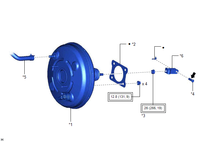
*1 | BRAKE BOOSTER ASSEMBLY |
*2 | BRAKE BOOSTER GASKET |
|
*3 | LOCK NUT |
*4 | PUSH ROD PIN |
|
*5 | UNION TO CHECK VALVE HOSE |
*6 | BRAKE MASTER CYLINDER PUSH ROD CLEVIS |
|
|
Tightening torque for "Major areas involving basic vehicle performance such as moving/turning/stopping" : N*m (kgf*cm, ft.*lbf) |
● | Non-reusable part |
.png) |
Lithium soap base glycol grease |
- | - |
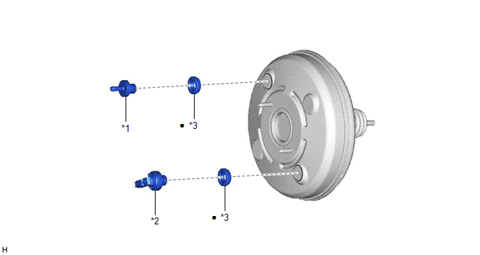
ILLUSTRATION
|
*1 | BRAKE VACUUM CHECK VALVE ASSEMBLY |
*2 | VACUUM WARNING SWITCH ASSEMBLY |
|
*3 | CHECK VALVE GROMMET |
- | - |
|
● | Non-reusable part |
- | - |
READ NEXT:
 On-vehicle Inspection
ON-VEHICLE INSPECTION PROCEDURE
1. INSPECT BRAKE BOOSTER ASSEMBLY (a) Airtightness check
(1) Start the engine and stop it after 1 or 2 minutes. Slowly depress the brake pedal several times.
Removal
REMOVAL CAUTION / NOTICE / HINT
The necessary procedures (adjustment, calibration, initialization or registration) that must be performed after parts are removed and installed, or replaced during br
Disassembly
DISASSEMBLY PROCEDURE 1. REMOVE BRAKE VACUUM CHECK VALVE ASSEMBLY
(a) Remove the brake vacuum check valve assembly from the brake booster assembly.
(b) Remove the check valve grommet from the brak
SEE MORE:
Dcm Activation
DCM ACTIVATION HINT: If the DCM (telematics transceiver) has been replaced, it is necessary to perform the Register Vehicle Information procedure.
DCM ACTIVATION (a) Connect the Techstream to the DLC3. (b) Turn the engine switch on (IG).
(c) Turn the Techstream on. (d) Choose "Telematics" from t
Parts Location
PARTS LOCATION ILLUSTRATION
*1 FRONT ENGINE MOUNTING INSULATOR
*2 REAR ENGINE MOUNTING INSULATOR
*3 CANISTER
*4 FUEL PUMP (for Low Pressure Side)
*5 MASS AIR FLOW METER SUB-ASSEMBLY
*6 PARK / NEUTRAL POSITION SWITCH ASSEMBLY
*7 VACUUM
