Toyota Camry (XV70): Components
COMPONENTS
ILLUSTRATION
.png)
|
*1 | REAR ENGINE UNDER COVER LH |
*2 | FRONT FENDER APRON SEAL LH |
|
*3 | NO. 1 ENGINE UNDER COVER |
*4 | FRONT WHEEL OPENING EXTENSION PAD LH |
|
*5 | FRONT WHEEL OPENING EXTENSION PAD RH |
- | - |
.png) |
N*m (kgf*cm, ft.*lbf): Specified torque |
- | - |
ILLUSTRATION
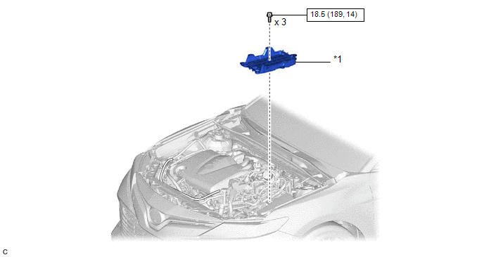
|
*1 | BATTERY CLAMP SUB-ASSEMBLY |
- | - |
|
|
N*m (kgf*cm, ft.*lbf): Specified torque |
- | - |
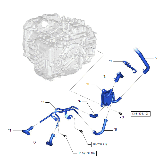
ILLUSTRATION
|
*1 | OUTLET NO. 1 OIL COOLER HOSE |
*2 | INLET NO. 1 OIL COOLER HOSE |
|
*3 | NO. 1 OIL COOLER TUBE SUB-ASSEMBLY WITHOUT HOSE |
*4 | INLET NO. 2 OIL COOLER HOSE |
|
*5 | OUTLET NO. 2 OIL COOLER HOSE |
*6 | NO. 1 WATER BY-PASS HOSE |
|
*7 | WATER BY-PASS HOSE ASSEMBLY |
*8 | TRANSMISSION OIL COOLER |
|
*9 | TRANSMISSION BREATHER CLAMP |
- | - |
|
|
N*m (kgf*cm, ft.*lbf): Specified torque |
- | - |
READ NEXT:
 Removal
REMOVAL CAUTION / NOTICE / HINT
The necessary procedures (adjustment, calibration, initialization or registration) that must be performed after parts are removed and installed, or replaced during tr
Installation
INSTALLATION PROCEDURE 1. INSTALL TRANSMISSION OIL COOLER
(a) Temporarily install the transmission oil cooler to the automatic transaxle case sub-assembly with the bolt (A).
SEE MORE:
Front seats
Adjustment procedure
Manual seat
Seat position adjustment lever
Seatback angle adjustment
lever
Vertical height adjustment lever
Power seat
Seat position adjustment switch
Seatback angle adjustment
switch
Seat cushion (front) angle
adjustment switch
Vertical height adju
VSC does not Operate or VSC does not Operate Correctly
DESCRIPTION When TRAC or VSC is operating, the skid control ECU (brake actuator assembly) blinks the slip indicator light to inform the driver that slippage occurred.
When a communication malfunction with the ECM is detected, TRAC and VSC are disabled. Also, TRAC and VSC are disabled when a DTC is
© 2023-2025 Copyright www.tocamry.com
