Toyota Camry (XV70): Components
COMPONENTS
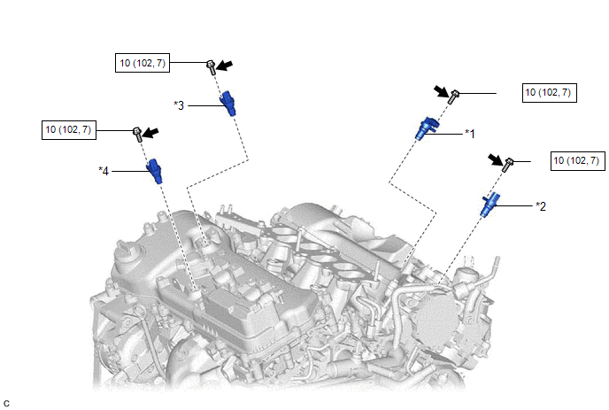
ILLUSTRATION
|
*1 | VVT SENSOR (for Intake Side of Bank 1) |
*2 | VVT SENSOR (for Exhaust Side of Bank 1) |
|
*3 | VVT SENSOR (for Intake Side of Bank 2) |
*4 | VVT SENSOR (for Exhaust Side of Bank 2) |
.png) |
N*m (kgf*cm, ft.*lbf): Specified torque |
.png) |
Adhesive 1324 |
|
★ | Precoated part |
- | - |
READ NEXT:
 Removal
REMOVAL CAUTION / NOTICE / HINT
The necessary procedures (adjustment, calibration, initialization or registration) that must be performed after parts are removed and installed, or replaced during VV
Installation
INSTALLATION PROCEDURE 1. INSTALL VVT SENSOR (for Exhaust Side of Bank 2)
(a) Apply a light coat of engine oil to the O-ring of the VVT sensor. NOTICE:
If reusing the VVT sensor, be sure to inspec
Crankshaft Position Sensor
ComponentsCOMPONENTS ILLUSTRATION
*1 CRANKSHAFT POSITION SENSOR
*2 CRANKSHAFT POSITION SENSOR PROTECTOR
N*m (kgf*cm, ft.*lbf): Specified torque
- - Remova
SEE MORE:
Low or High Power Supply Voltage (C1241)
DESCRIPTION If a malfunction in the power source circuit occurs, or a malfunction in communication with the skid control ECU (brake actuator assembly) or in a speed sensor occurs, the 4WD ECU assembly will prohibit operations by the fail-safe function.
DTC No. Detection Item
DTC Detecti
Ultrasonic Sensor (Front Left Corner) Component Internal Failure (C1AE196)
DESCRIPTION The front corner ultrasonic sensor LH is installed on the front bumper. The clearance warning ECU assembly detects obstacles based on signals it receives from the front corner ultrasonic sensor LH. If an open circuit or other malfunction occurs in the front corner ultrasonic sensor LH, t
© 2023-2025 Copyright www.tocamry.com
