Toyota Camry (XV70): Disassembly
DISASSEMBLY
PROCEDURE
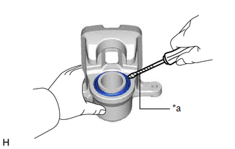
1. REMOVE CYLINDER BOOT
| (a) Using a screwdriver with its tip wrapped with protective tape, remove the rear disc brake piston set ring and cylinder boot from the rear disc brake cylinder. NOTICE: Be careful not to damage the rear disc brake piston and rear disc brake cylinder. |
|
2. REMOVE REAR DISC BRAKE PISTON
| (a) Place a piece of cloth between the rear disc brake piston and rear disc brake cylinder. |
|
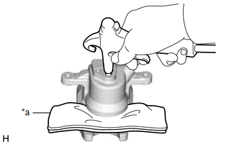
(b) Apply compressed air to remove the rear disc brake piston from the rear disc brake cylinder.
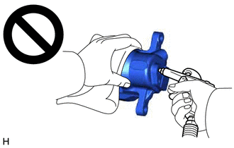
CAUTION:
- Do not hold the rear disc brake cylinder with any part of your hand between the rear disc brake cylinder and rear disc brake piston.
- Do not place any part of your hand in front of the rear disc brake piston when using compressed air as a severe injury may result.
NOTICE:
Do not allow any brake fluid to spatter.
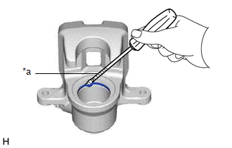
3. REMOVE PISTON SEAL
|
(a) Using a screwdriver with its tip wrapped with protective tape, remove the piston seal from the rear disc brake cylinder. NOTICE: Do not damage the inner surface or piston seal groove of the rear disc brake cylinder. |
|
4. REMOVE REAR DISC BRAKE BLEEDER PLUG CAP
(a) Remove the rear disc brake bleeder plug cap from the rear disc brake bleeder plug.
5. REMOVE REAR DISC BRAKE BLEEDER PLUG
(a) Remove the rear disc brake bleeder plug from the rear disc brake cylinder.
READ NEXT:
 Inspection
INSPECTION PROCEDURE 1. INSPECT BRAKE CYLINDER AND PISTON
(a) Check the rear disc brake cylinder bore and rear disc brake piston for rust and scoring. If necessary, replace the rear disc brake cylin
Reassembly
REASSEMBLY PROCEDURE 1. TEMPORARILY TIGHTEN REAR DISC BRAKE BLEEDER PLUG
(a) Temporarily install the rear disc brake bleeder plug to the rear disc brake cylinder.
HINT: Fully tighten the rear disc
Installation
INSTALLATION CAUTION / NOTICE / HINT
NOTICE:
Immediately after installing the brake pads, the braking performance may be reduced. Always perform a road test in a safe place while paying attentio
SEE MORE:
Removal
REMOVAL CAUTION / NOTICE / HINT
The necessary procedures (adjustment, calibration, initialization, or registration) that must be performed after parts are removed and installed, or replaced during front axle hub sub-assembly removal/installation are shown below. Necessary Procedures After Parts Re
Removal
REMOVAL CAUTION / NOTICE / HINT
The necessary procedures (adjustment, calibration, initialization, or registration) that must be performed after parts are removed and installed, or replaced during rear stereo component speaker assembly removal/installation are shown below. Necessary Procedure Afte
