Toyota Camry (XV70): Disassembly
DISASSEMBLY
CAUTION / NOTICE / HINT
NOTICE:
- When using a vise, place aluminum plates between the part and vise.
- When using a vise, do not overtighten it.
HINT:
- Use the same procedure for the RH and LH sides.
- The procedure listed below is for the LH side.
PROCEDURE
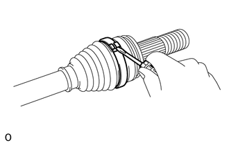
1. REMOVE REAR NO. 2 DRIVE SHAFT INBOARD JOINT BOOT CLAMP LH
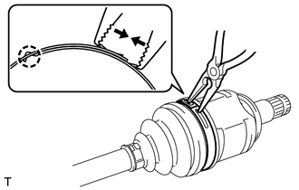
(a) for Type A:
| (1) Using needle-nose pliers, remove the rear No. 2 drive shaft inboard joint boot clamp LH as shown in the illustration. |
|
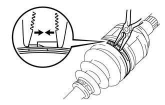
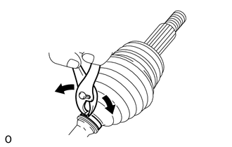
(b) for Type B:
| (1) Using needle-nose pliers, remove the rear No. 2 drive shaft inboard joint boot clamp LH as shown in the illustration. |
|
2. REMOVE REAR DRIVE SHAFT INBOARD JOINT BOOT CLAMP LH
HINT:
Use the same procedure described for the rear No. 2 drive shaft inboard joint boot clamp LH.
3. DISCONNECT INBOARD JOINT BOOT
(a) Disconnect the inboard joint boot from the rear drive shaft inboard joint assembly LH.
4. REMOVE REAR DRIVE SHAFT INBOARD JOINT ASSEMBLY LH
|
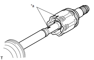
*a | Matchmark |
(a) Remove any old grease from the rear drive shaft inboard joint assembly LH.
(b) Put matchmarks on the rear drive shaft inboard joint assembly LH and rear drive outboard joint shaft assembly LH.
NOTICE:
Do not use a punch to make the matchmarks.
(c) Remove the rear drive shaft inboard joint assembly LH from the rear drive outboard joint shaft assembly LH.
| (d) Using a snap ring expander, remove the rear drive shaft snap ring LH. |
|
| (e) Put matchmarks on the rear drive outboard joint shaft assembly LH and tripod joint. NOTICE: Do not use a punch to make the matchmarks. |
|
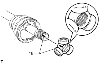
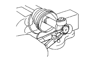
(f) Using a brass bar and hammer, remove the tripod joint from the rear drive outboard joint shaft assembly LH.
NOTICE:
- Do not tap the rollers.
- Do not drop the tripod joint.
(g) Remove the inboard joint boot.
5. REMOVE REAR NO. 2 DRIVE SHAFT OUTBOARD JOINT BOOT CLAMP LH
(a) Using a screwdriver, remove the rear No. 2 drive shaft outboard joint boot clamp LH as shown in the illustration.
6. REMOVE REAR DRIVE SHAFT OUTBOARD JOINT BOOT CLAMP LH
(a) Using pliers, remove the rear drive shaft outboard joint boot clamp LH as shown in the illustration.
7. REMOVE OUTBOARD JOINT BOOT
(a) Remove the outboard joint boot from the rear drive outboard joint shaft assembly LH.
(b) Remove any old grease from the rear drive outboard joint shaft assembly LH.
READ NEXT:
 Inspection
INSPECTION CAUTION / NOTICE / HINT
NOTICE:
When using a vise, place aluminum plates between the part and vise.
When using a vise, do not overtighten it.
PROCEDURE 1. INSPECT REAR DRIVE S
Reassembly
REASSEMBLY CAUTION / NOTICE / HINT
NOTICE:
When using a vise, place aluminum plates between the part and vise.
When using a vise, do not overtighten it.
HINT:
Use the same procedure
Installation
INSTALLATION CAUTION / NOTICE / HINT
HINT:
Use the same procedure for the RH and LH sides.
The procedure listed below is for the LH side.
PROCEDURE 1. INSTALL REAR DRIVE SHAFT INBOARD JO
SEE MORE:
EVAP System
RELATED DTCS
DTC No. SAE
Monitoring Item Link
P00FE00 P00FE
EVAP vent line blocked
P043E00 P043E
Reference orifice clogged (built into canister pump module)
P043F00 P043F
Reference orifice high-flow (built into canister
Stereo Jack Adapter Assembly
ComponentsCOMPONENTS ILLUSTRATION
*1 LOWER CENTER INSTRUMENT PANEL FINISH PANEL
*2 NO. 1 METER HOOD CLUSTER
*3 NO. 1 STEREO JACK ADAPTER ASSEMBLY
- - RemovalREMOVAL PROCEDURE
1. REMOVE NO. 1 METER HOOD CLUSTER Click here
2. REMOVE LOWER CENTER IN
