Toyota Camry (XV70): Indicator (Red) Circuit Short to Ground (B157011,B157013)
DESCRIPTION
This DTC is stored when the DCM (telematics transceiver) detects an open or short in the manual (SOS) switch red indicator circuit of the manual (SOS) switch.
The manual (SOS) switch red indicator illuminates for 2 seconds and goes off when the engine switch is turned on (IG). If a malfunction in the safety connect system is detected, the manual (SOS) switch red indicator will illuminate.
However, the manual (SOS) switch red indicator may not illuminate when this DTC is set.
|
DTC No. | Detection Item |
DTC Detection Condition | Trouble Area |
|---|---|---|---|
|
B157011 | Indicator (Red) Circuit Short to Ground |
Manual (SOS) switch red indicator impedance (Ω) is lower than the malfunction threshold for 10 seconds or more when the engine switch is on (IG) |
|
| B157013 |
Indicator (Red) Circuit Open |
Manual (SOS) switch red indicator impedance (Ω) is higher than the malfunction threshold for 10 seconds or more when the engine switch is on (IG) |
|
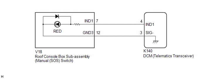
WIRING DIAGRAM
w/ Sliding Roof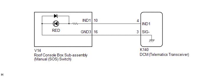 w/o Sliding Roof
CAUTION / NOTICE / HINT
NOTICE:
Depending on the parts that are replaced during vehicle inspection or maintenance, performing initialization, registration or calibration may be needed. Refer to Precaution for Safety Connect System.
Click here .gif)
HINT:
If DTC B157011 or B157013 is stored, the manual (SOS) switch red indicator may not illuminate when another DTC is stored.
PROCEDURE
| 1. |
CHECK DTC |
(a) Turn the engine switch off.
(b) Connect the Techstream to the DLC3.
(c) Turn the engine switch on (IG) and wait for 10 seconds or more.
(d) Turn the Techstream on.
(e) Clear the DTCs.
Body Electrical > Telematics > Clear DTCs(f) Check for DTCs and check that no DTCs are output.
Body Electrical > Telematics > Trouble CodesOK:
No DTCs are output.
| OK | .gif) |
USE SIMULATION METHOD TO CHECK |
|
.gif)
| 2. |
CONFIRM MODEL |
(a) Choose the model to be inspected.
| Result |
Proceed to |
|---|---|
| w/ Sliding Roof |
A |
| w/o Sliding Roof |
B |
| B |
| GO TO STEP 5 |
|
| 3. |
INSPECT ROOF CONSOLE BOX SUB-ASSEMBLY (MANUAL (SOS) SWITCH) (RED INDICATOR) |
| (a) Remove the roof console box sub-assembly (manual (SOS) switch). Click here |
|
(b) Connect 2 dry-cell batteries (1.5 V each) in series.
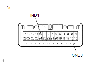
(c) Connect a positive (+) lead from the batteries to terminal 10 (IND1) and a negative (-) lead to terminal 16 (GND3) of the roof console box sub-assembly (manual (SOS) switch) connector.
(d) Check if the manual (SOS) switch red indicator illuminates.
OK:
Manual (SOS) switch red indicator illuminates.
| NG | | REPLACE ROOF CONSOLE BOX SUB-ASSEMBLY (MANUAL (SOS) SWITCH) |
|
| 4. |
CHECK HARNESS AND CONNECTOR (DCM (TELEMATICS TRANSCEIVER) - ROOF CONSOLE BOX SUB-ASSEMBLY (MANUAL (SOS) SWITCH)) |
(a) Disconnect the K140 DCM (telematics transceiver) connector.
(b) Disconnect the V14 roof console box sub-assembly (manual (SOS) switch) connector.
(c) Measure the resistance according to the value(s) in the table below.
Standard Resistance:
|
Tester Connection | Condition |
Specified Condition |
|---|---|---|
|
K140-4 (IND1) - V14-10 (IND1) |
Always | Below 1 Ω |
|
K140-4 (IND1) or V14-10 (IND1) - Body ground |
Always | 10 kΩ or higher |
|
K140-3 (SIG-) - V14-16 (GND3) |
Always | Below 1 Ω |
|
K140-3 (SIG-) or V14-16 (GND3) - Body ground |
Always | 10 kΩ or higher |
| OK | | GO TO STEP 7 |
| NG | | REPAIR OR REPLACE HARNESS OR CONNECTOR |
| 5. |
INSPECT ROOF CONSOLE BOX SUB-ASSEMBLY (MANUAL (SOS) SWITCH) (RED INDICATOR) |
| (a) Remove the roof console box sub-assembly (manual (SOS) switch). Click here |
|
(b) Connect 2 dry-cell batteries (1.5 V each) in series.
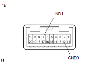
(c) Connect a positive (+) lead from the batteries to terminal 7 (IND1) and a negative (-) lead to terminal 12 (GND3) of the roof console box sub-assembly (manual (SOS) switch) connector.
(d) Check if the manual (SOS) switch red indicator illuminates.
OK:
Manual (SOS) switch red indicator illuminates.
| NG | | REPLACE ROOF CONSOLE BOX SUB-ASSEMBLY (MANUAL (SOS) SWITCH) |
|
| 6. |
CHECK HARNESS AND CONNECTOR (DCM (TELEMATICS TRANSCEIVER) - ROOF CONSOLE BOX SUB-ASSEMBLY (MANUAL (SOS) SWITCH)) |
(a) Disconnect the K140 DCM (telematics transceiver) connector.
(b) Disconnect the V18 roof console box sub-assembly (manual (SOS) switch) connector.
(c) Measure the resistance according to the value(s) in the table below.
Standard Resistance:
|
Tester Connection | Condition |
Specified Condition |
|---|---|---|
|
K140-4 (IND1) - V18-7 (IND1) |
Always | Below 1 Ω |
|
K140-4 (IND1) or V18-7 (IND1) - Body ground |
Always | 10 kΩ or higher |
|
K140-3 (SIG-) - V18-12 (GND3) |
Always | Below 1 Ω |
|
K140-3 (SIG-) or V18-12 (GND3) - Body ground |
Always | 10 kΩ or higher |
| NG | | REPAIR OR REPLACE HARNESS OR CONNECTOR |
|
| 7. |
REPLACE DCM (TELEMATICS TRANSCEIVER) |
(a) Replace the DCM (telematics transceiver) with a new one.
Click here
NOTICE:
- The engine switch must be off.
- Do not exchange the DCM (telematics transceiver) with one from another vehicle.
| NEXT | | PERFORM DCM ACTIVATION |
READ NEXT:
 Indicator (Green) Circuit Short to Ground (B157111,B157113)
DESCRIPTION This DTC is set when the DCM (telematics transceiver) detects an open or short in the manual (SOS) switch green indicator circuit of the manual (SOS) switch. The manual (SOS) switch green
Microphone Circuit Open (B157213)
DESCRIPTION This DTC is stored when the DCM (telematics transceiver) detects a malfunction in the telephone microphone assembly circuit.
DTC No. Detection Item
DTC Detection Condition T
DCM System Internal Failure (B15A804)
DESCRIPTION This DTC is stored when an internal circuit malfunction is detected by the DCM (telematics transceiver) self check.
DTC No. Detection Item
DTC Detection Condition Trouble Ar
SEE MORE:
Right Front Wheel ABS Hold Solenoid Control Circuit Short to Battery (C12BB12,...,C12C649)
DESCRIPTION The ABS solenoid relay and solenoid valves are built into the brake actuator assembly.
The front solenoid valve RH controls the brake fluid pressure of the front wheel cylinder RH of the vehicle.
When this DTC is stored, the fail-safe function operates and the ABS solenoid relay is t
Components
COMPONENTS ILLUSTRATION
*1 V-BANK COVER SUB-ASSEMBLY
*2 AIR FUEL RATIO SENSOR (for Bank 1)
*3 AIR FUEL RATIO SENSOR (for Bank 2)
- -
N*m (kgf*cm, ft.*lbf): Specified torque
* For use with SST
