Toyota Camry (XV70): Left Rear Wheel Speed Sensor Circuit Short to Ground or Open (C050C14)
DESCRIPTION
Refer to DTC C050C12
Click here
.gif)
|
DTC No. | Detection Item |
DTC Detection Condition | Trouble Area |
|---|---|---|---|
|
C050C14 | Left Rear Wheel Speed Sensor Circuit Short to Ground or Open |
A short or open circuit is detected in the speed sensor signal circuit for 0.12 seconds or more. |
|
|
Vehicle Condition | |||
|---|---|---|---|
|
Pattern 1 | Pattern 2 | ||
|
Diagnosis Condition | - |
- | - |
|
Malfunction Status | An open circuit is detected in the speed sensor signal circuit. |
○ | - |
|
A short circuit is detected in the speed sensor signal circuit. |
- | ○ | |
|
Detection Time | 0.12 seconds or more. |
0.12 seconds or more. | |
|
Number of Trips | 1 trip |
1 trip | |
HINT:
DTC will be output when conditions for either of the patterns in the table above are met.
WIRING DIAGRAM
Refer to DTC C050C12.
Click here
CAUTION / NOTICE / HINT
NOTICE:
- After replacing the skid control ECU (brake actuator assembly), perform acceleration sensor zero point calibration and system information memorization.
Click here
- After replacing or removing and installing a speed sensor, perform Dealer Mode (Signal Check) inspection to confirm that the speed sensors are operating correctly.
Click here
PROCEDURE
|
1. | CHECK HARNESS AND CONNECTOR (SENSOR GROUND CIRCUIT) |
| (a) Make sure that there is no looseness at the locking part and the connecting part of the connectors. OK: The connector is securely connected. |
|
.png)
(b) Disconnect the g1 rear speed sensor LH (rear axle hub and bearing assembly LH) connector.
(c) Check both the connector case and the terminals for deformation and corrosion.
OK:
No deformation or corrosion.
(d) Turn the ignition switch to ON.
(e) Measure the voltage according to the value(s) in the table below.
Standard Voltage:
|
Tester Connection | Condition |
Specified Condition |
|---|---|---|
|
g1-2 (RL+) - g1-1 (RL-) |
Ignition switch ON | 11 to 14 V |
| NG | .gif) | GO TO STEP 4 |
|
.gif)
| 2. |
INSPECT SKID CONTROL SENSOR WIRE LH |
| (a) Make sure that there is no looseness at the locking part and the connecting part of the connectors. OK: The connector is securely connected. |
|
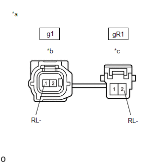
(b) Disconnect the g1 skid control sensor wire LH connector.
(c) Disconnect the gR1 skid control sensor wire LH connector.
(d) Check both the connector case and the terminals for deformation and corrosion.
OK:
No deformation or corrosion.
(e) Measure the resistance according to the value(s) in the table below.
Standard Resistance:
|
Tester Connection | Condition |
Specified Condition |
|---|---|---|
|
g1-1 (RL-) or gR1-2 (RL-) - Body ground and other terminals |
Always | 10 kΩ or higher |
| NG | | REPLACE SKID CONTROL SENSOR WIRE LH |
|
| 3. |
CHECK HARNESS AND CONNECTOR (SKID CONTROL SENSOR WIRE LH - BRAKE ACTUATOR ASSEMBLY) |
(a) Make sure that there is no looseness at the locking part and the connecting part of the connectors.
OK:
The connector is securely connected.
(b) Disconnect the A33 skid control ECU (brake actuator assembly) connector.
(c) Disconnect the gR1 skid control sensor wire LH connector.
(d) Check both the connector case and the terminals for deformation and corrosion.
OK:
No deformation or corrosion.
(e) Measure the resistance according to the value(s) in the table below.
Standard Resistance:
|
Tester Connection | Condition |
Specified Condition |
|---|---|---|
|
gR1-2 (RL-) or A33-18 (RL-) - Body ground |
Always | 10 kΩ or higher |
| OK | | REPLACE REAR AXLE HUB AND BEARING ASSEMBLY LH |
| NG | | REPAIR OR REPLACE HARNESS OR CONNECTOR |
| 4. |
INSPECT SKID CONTROL SENSOR WIRE LH |
| (a) Make sure that there is no looseness at the locking part and the connecting part of the connectors. OK: The connector is securely connected. |
|
(b) Disconnect the g1 skid control sensor wire LH connector.
(c) Disconnect the gR1 skid control sensor wire LH connector.
(d) Check both the connector case and the terminals for deformation and corrosion.
OK:
No deformation or corrosion.
(e) Measure the resistance according to the value(s) in the table below.
Standard Resistance:
|
Tester Connection | Condition |
Specified Condition |
|---|---|---|
|
g1-1 (RL-) - gR1-2 (RL-) |
Always | Below 1 Ω |
| NG | | REPLACE SKID CONTROL SENSOR WIRE LH |
|
| 5. |
CHECK HARNESS AND CONNECTOR (SKID CONTROL SENSOR WIRE LH - BRAKE ACTUATOR ASSEMBLY) |
(a) Make sure that there is no looseness at the locking part and the connecting part of the connectors.
OK:
The connector is securely connected.
(b) Disconnect the A33 skid control ECU (brake actuator assembly) connector.
(c) Disconnect the gR1 skid control sensor wire LH connector.
(d) Check both the connector case and the terminals for deformation and corrosion.
OK:
No deformation or corrosion.
(e) Measure the resistance according to the value(s) in the table below.
Standard Resistance:
|
Tester Connection | Condition |
Specified Condition |
|---|---|---|
|
gR1-2 (RL-) - A33-18 (RL-) |
Always | Below 1 Ω |
| OK | | REPLACE BRAKE ACTUATOR ASSEMBLY |
| NG | | REPAIR OR REPLACE HARNESS OR CONNECTOR |
READ NEXT:
 Left Rear Wheel Speed Sensor Circuit Voltage Out of Range (C050C1C)
DESCRIPTION Refer to DTC C050C12 Click here
DTC No. Detection Item
DTC Detection Condition Trouble Area
C050C1C Left Rear Wheel Speed Sensor Circuit Voltage Out of Range
Left Rear Wheel Speed Sensor Circuit Intermittent (C050C1F)
DESCRIPTION Refer to DTC C050C12 Click here
DTC No. Detection Item
DTC Detection Condition Trouble Area
C050C1F Left Rear Wheel Speed Sensor Circuit Intermittent
Left Rear Wheel Speed Sensor Signal Stuck Low (C050C23)
DESCRIPTION Refer to DTC C050C12 Click here
DTC No. Detection Item
DTC Detection Condition Trouble Area
C050C23 Left Rear Wheel Speed Sensor Signal Stuck Low
Wh
SEE MORE:
Alarm
The alarm
The alarm uses light and sound to give an alert when an intrusion is
detected.
The alarm is triggered in the following situations when the alarm is
set:
Vehicles without a smart key system
A locked door is unlocked or opened in any way other than using
the wireless remote cont
Test Mode Procedure
TEST MODE PROCEDURE SENSOR CHECK USING DEALER MODE (SIGNAL CHECK)
NOTICE:
After replacing or removing and installing a speed sensor, perform Dealer Mode (Signal Check) inspection to confirm that the speed sensors are operating correctly.
After replacing or removing and installing a speed
