Toyota Camry (XV70): Left Rear Wheel Speed Sensor Internal Electronic Failure (C050C49)
DESCRIPTION
When the system is starting up and the skid control ECU (brake actuator assembly) detects a speed sensor circuit malfunction via the speed sensor circuit self-diagnosis function, this DTC is stored.
|
DTC No. | Detection Item |
DTC Detection Condition | Trouble Area |
|---|---|---|---|
|
C050C49 | Left Rear Wheel Speed Sensor Internal Electronic Failure |
A circuit malfunction in the speed sensor is detected during the self test. |
|
WIRING DIAGRAM
Refer to DTC C050C12.
Click here
.gif)
CAUTION / NOTICE / HINT
NOTICE:
- After replacing the skid control ECU (brake actuator assembly), perform acceleration sensor zero point calibration and system information memorization.
Click here
- After replacing or removing and installing a speed sensor, perform Dealer Mode (Signal Check) inspection to confirm that the speed sensors are operating correctly.
Click here
PROCEDURE
|
1. | CHECK HARNESS AND CONNECTOR (SENSOR CIRCUIT) |
| (a) Make sure that there is no looseness at the locking part and the connecting part of the connectors. OK: The connector is securely connected. |
|
.png)
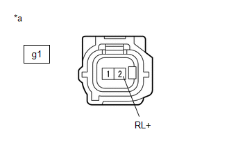
(b) Disconnect the g1 rear speed sensor LH (rear axle hub and bearing assembly LH) connector.
(c) Check both the connector case and the terminals for deformation and corrosion.
OK:
No deformation or corrosion.
(d) Turn the ignition switch to ON.
(e) Measure the voltage according to the value(s) in the table below.
Standard Voltage:
|
Tester Connection | Condition |
Specified Condition |
|---|---|---|
|
g1-2 (RL+) - g1-1 (RL-) |
Ignition switch ON | 11 to 14 V |
| NG | .gif) | GO TO STEP 7 |
|
.gif)
| 2. |
CHECK HARNESS AND CONNECTOR (SENSOR POWER SOURCE CIRCUIT) |
| (a) Make sure that there is no looseness at the locking part and the connecting part of the connectors. OK: The connector is securely connected. |
|
(b) Disconnect the g1 rear speed sensor LH (rear axle hub and bearing assembly LH) connector.
(c) Check both the connector case and the terminals for deformation and corrosion.
OK:
No deformation or corrosion.
(d) Measure the voltage according to the value(s) in the table below.
Standard Voltage:
|
Tester Connection | Condition |
Specified Condition |
|---|---|---|
|
g1-2 (RL+) - Body ground |
Ignition switch off | Below 1.5 V |
| NG | | GO TO STEP 5 |
|
| 3. |
INSPECT SKID CONTROL SENSOR WIRE LH |
| (a) Make sure that there is no looseness at the locking part and the connecting part of the connectors. OK: The connector is securely connected. |
|
.png)
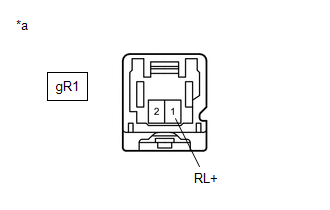
(b) Disconnect the g1 skid control sensor wire LH connector.
(c) Disconnect the gR1 skid control sensor wire LH connector.
(d) Check both the connector case and the terminals for deformation and corrosion.
OK:
No deformation or corrosion.
(e) Measure the resistance according to the value(s) in the table below.
Standard Resistance:
|
Tester Connection | Condition |
Specified Condition |
|---|---|---|
|
g1-1 (RL-) or gR1-2 (RL-) - Body ground and other terminals |
Always | 10 kΩ or higher |
| NG | | REPLACE SKID CONTROL SENSOR WIRE LH |
|
| 4. |
CHECK HARNESS AND CONNECTOR (SKID CONTROL SENSOR WIRE LH - BRAKE ACTUATOR ASSEMBLY) |
(a) Make sure that there is no looseness at the locking part and the connecting part of the connectors.
OK:
The connector is securely connected.
(b) Disconnect the A33 skid control ECU (brake actuator assembly) connector.
(c) Disconnect the gR1 skid control sensor wire LH connector.
(d) Check both the connector case and the terminals for deformation and corrosion.
OK:
No deformation or corrosion.
(e) Measure the resistance according to the value(s) in the table below.
Standard Resistance:
|
Tester Connection | Condition |
Specified Condition |
|---|---|---|
|
gR1-2 (RL-) or A33-18 (RL-) - Body ground |
Always | 10 kΩ or higher |
| OK | | REPLACE REAR AXLE HUB AND BEARING ASSEMBLY LH |
| NG | | REPAIR OR REPLACE HARNESS OR CONNECTOR |
| 5. |
CHECK HARNESS AND CONNECTOR (SENSOR POWER SOURCE CIRCUIT) |
| (a) Make sure that there is no looseness at the locking part and the connecting part of the connectors. OK: The connector is securely connected. |
|
(b) Disconnect the gR1 skid control sensor wire LH connector.
(c) Check both the connector case and the terminals for deformation and corrosion.
OK:
No deformation or corrosion.
(d) Measure the voltage according to the value(s) in the table below.
Standard Voltage:
|
Tester Connection | Condition |
Specified Condition |
|---|---|---|
|
gR1-1 (RL+) - Body ground |
Ignition switch off | Below 1.5 V |
| OK | | REPLACE SKID CONTROL SENSOR WIRE LH |
|
| 6. |
CHECK HARNESS AND CONNECTOR (SKID CONTROL SENSOR WIRE LH - BRAKE ACTUATOR ASSEMBLY) |
| (a) Make sure that there is no looseness at the locking part and the connecting part of the connectors. OK: The connector is securely connected. |
|
(b) Disconnect the A33 skid control ECU (brake actuator assembly) connector.
(c) Disconnect the gR1 skid control sensor wire LH connector.
(d) Check both the connector case and the terminals for deformation and corrosion.
OK:
No deformation or corrosion.
(e) Measure the voltage according to the value(s) in the table below.
Standard Voltage:
|
Tester Connection | Condition |
Specified Condition |
|---|---|---|
|
gR1-1 (RL+) - Body ground |
Always | Below 1.5 V |
| OK | | REPLACE BRAKE ACTUATOR ASSEMBLY |
| NG | | REPAIR OR REPLACE HARNESS OR CONNECTOR |
| 7. |
CHECK HARNESS AND CONNECTOR (SENSOR CIRCUIT) |
| (a) Make sure that there is no looseness at the locking part and the connecting part of the connectors. OK: The connector is securely connected. |
|
.png)
(b) Disconnect the gR1 skid control sensor wire LH connector.
(c) Check both the connector case and the terminals for deformation and corrosion.
OK:
No deformation or corrosion.
(d) Turn the ignition switch to ON.
(e) Measure the voltage according to the value(s) in the table below.
Standard Voltage:
|
Tester Connection | Condition |
Specified Condition |
|---|---|---|
|
gR1-1 (RL+) - gR1-2 (RL-) |
Ignition switch ON | 11 to 14 V |
| OK | | REPLACE SKID CONTROL SENSOR WIRE LH |
|
| 8. |
CHECK HARNESS AND CONNECTOR (SENSOR POWER SOURCE CIRCUIT) |
| (a) Make sure that there is no looseness at the locking part and the connecting part of the connectors. OK: The connector is securely connected. |
|
(b) Disconnect the gR1 skid control sensor wire LH connector.
(c) Check both the connector case and the terminals for deformation and corrosion.
OK:
No deformation or corrosion.
(d) Turn the ignition switch to ON.
(e) Measure the voltage according to the value(s) in the table below.
Standard Voltage:
|
Tester Connection | Condition |
Specified Condition |
|---|---|---|
|
gR1-1 (RL+) - Body ground |
Ignition switch ON | 11 to 14 V |
| NG | | GO TO STEP 11 |
|
| 9. |
CHECK HARNESS AND CONNECTOR (SKID CONTROL SENSOR WIRE LH - BRAKE ACTUATOR ASSEMBLY) |
| (a) Make sure that there is no looseness at the locking part and the connecting part of the connectors. OK: The connector is securely connected. |
|
.png)
(b) Disconnect the A33 skid control ECU (brake actuator assembly) connector.
(c) Disconnect the gR1 skid control sensor wire LH connector.
(d) Check both the connector case and the terminals for deformation and corrosion.
OK:
No deformation or corrosion.
(e) Measure the voltage according to the value(s) in the table below.
Standard Voltage:
|
Tester Connection | Condition |
Specified Condition |
|---|---|---|
|
gR1-2 (RL-) - Body ground |
Always | Below 1.5 V |
| NG | | REPAIR OR REPLACE HARNESS OR CONNECTOR |
|
| 10. |
CHECK HARNESS AND CONNECTOR (SKID CONTROL SENSOR WIRE LH - BRAKE ACTUATOR ASSEMBLY) |
(a) Make sure that there is no looseness at the locking part and the connecting part of the connectors.
OK:
The connector is securely connected.
(b) Disconnect the A33 skid control ECU (brake actuator assembly) connector.
(c) Disconnect the gR1 skid control sensor wire LH connector.
(d) Check both the connector case and the terminals for deformation and corrosion.
OK:
No deformation or corrosion.
(e) Measure the resistance according to the value(s) in the table below.
Standard Resistance:
|
Tester Connection | Condition |
Specified Condition |
|---|---|---|
|
gR1-2 (RL-) - A33-18 (RL-) |
Always | Below 1 Ω |
|
gR1-1 (RL+) or A33-31 (RL+) - gR1-2 (RL-) or A33-18 (RL-) |
Always | 10 kΩ or higher |
| OK | | REPLACE BRAKE ACTUATOR ASSEMBLY |
| NG | | REPAIR OR REPLACE HARNESS OR CONNECTOR |
| 11. |
CHECK HARNESS AND CONNECTOR (SKID CONTROL SENSOR WIRE LH - BRAKE ACTUATOR ASSEMBLY) |
(a) Make sure that there is no looseness at the locking part and the connecting part of the connectors.
OK:
The connector is securely connected.
(b) Disconnect the A33 skid control ECU (brake actuator assembly) connector.
(c) Disconnect the gR1 skid control sensor wire LH connector.
(d) Check both the connector case and the terminals for deformation and corrosion.
OK:
No deformation or corrosion.
(e) Measure the resistance according to the value(s) in the table below.
Standard Resistance:
|
Tester Connection | Condition |
Specified Condition |
|---|---|---|
|
gR1-1 (RL+) - A33-31 (RL+) |
Always | Below 1 Ω |
|
gR1-1 (RL+) or A33-31 (RL+) - Body ground |
Always | 10 kΩ or higher |
| OK | | REPLACE BRAKE ACTUATOR ASSEMBLY |
| NG | | REPAIR OR REPLACE HARNESS OR CONNECTOR |
READ NEXT:
 Right Rear Wheel Speed Sensor Circuit Short to Battery (C051212)
DESCRIPTION Each speed sensor detects wheel speed and sends signals to the skid control ECU (brake actuator assembly). These signals are used by the ABS control.
The speed sensor detects the magneti
Right Rear Wheel Speed Sensor Circuit Short to Ground or Open (C051214)
DESCRIPTION Refer to DTC C051212 Click here
DTC No. Detection Item
DTC Detection Condition Trouble Area
C051214 Right Rear Wheel Speed Sensor Circuit Short to Ground or Op
Right Rear Wheel Speed Sensor Circuit Voltage Out of Range (C05121C)
DESCRIPTION Refer to DTC C051212 Click here
DTC No. Detection Item
DTC Detection Condition Trouble Area
C05121C Right Rear Wheel Speed Sensor Circuit Voltage Out of Range
SEE MORE:
Alarm
The alarm
The alarm uses light and sound to give an alert when an intrusion is
detected.
The alarm is triggered in the following situations when the alarm is
set:
Vehicles without a smart key system
A locked door is unlocked or opened in any way other than using
the wireless remote cont
Actuator Supply Voltage "A" Stuck On (P06579E)
MONITOR DESCRIPTION The ECM monitors the output voltage to the throttle actuator. This self-check ensures that the ECM is functioning properly. The output voltage is usually 0 V when the engine switch is turned off. If the output voltage is 7 V or higher when the engine switch is turned off, the ECM
