Toyota Camry (XV70): Lost Communication with Blind Spot Monitor Slave Module (U0232)
DESCRIPTION
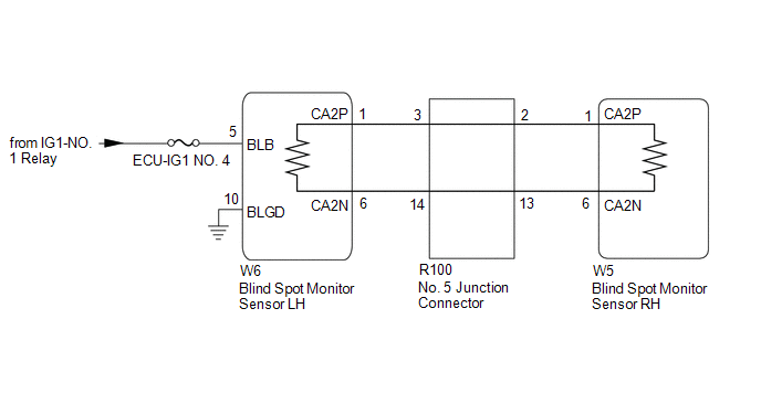
This DTC is stored when the blind spot monitor sensor RH judges that there is a communication problem with the blind spot monitor sensor LH.
|
DTC No. | Detection Item |
DTC Detection Condition | Trouble Area |
|---|---|---|---|
|
U0232 | Lost Communication with Blind Spot Monitor Slave Module |
The blind spot monitor sensor (master) cannot receive signals from the blind spot monitor sensor (slave) |
|
WIRING DIAGRAM
CAUTION / NOTICE / HINT
NOTICE:
- When checking for DTCs, make sure that the blind spot monitor system is turned on.
- Inspect the fuses for circuits related to this system before performing the following procedure.
- Before measuring the resistance of the CAN bus, turn the engine switch off and leave the vehicle for 1 minute or more without operating the key or any switches, or opening or closing the doors. After that, disconnect the cable from the negative (-) battery terminal and leave the vehicle for 1 minute or more before measuring the resistance.
- After turning the engine switch off, waiting time may be required before disconnecting the cable from the negative (-) battery terminal. Therefore, make sure to read the disconnecting the cable from the negative (-) battery terminal notices before proceeding with work.
Click here
.gif)
HINT:
- Operating the engine switch, any other switches or a door triggers related ECU and sensor communication on the CAN. This communication will cause the resistance value to change.
- Even after DTCs are cleared, if a DTC is stored again after driving the vehicle for a while, the malfunction may be occurring due to vibration of the vehicle. In such a case, wiggling the ECUs or wire harness while performing the inspection below may help determine the cause of the malfunction.
PROCEDURE
|
1. | CONFIRM MODEL |
(a) Choose the model to be inspected.
|
Result | Proceed to |
|---|---|
|
w/ Parking Support Brake System |
A |
| w/o Parking Support Brake System |
B |
| B |
.gif) | GO TO STEP 3 |
|
.gif)
| 2. |
CHECK DTC OUTPUT (PARKING SUPPORT BRAKE SYSTEM) |
(a) Using the Techstream, check for DTCs according to the prompts on the screen.
Body Electrical > Clearance Warning > Trouble CodesStandard:
The clearance warning ECU assembly does not output DTCs U117787 and U117887 simultaneously.
| NG | | GO TO PARKING SUPPORT BRAKE SYSTEM (DTC U117787) |
|
| 3. |
CHECK CAN BUS MAIN WIRE |
(a) Turn the engine switch off.
(b) Disconnect the cable from the negative (-) battery terminal.
| (c) Measure the resistance according to the value(s) in the table below. Standard Resistance:
|
|
(d) Reconnect the cable to the negative (-) battery terminal.
|
Result | Proceed to |
|---|---|
|
OK | A |
|
Open circuit in CAN main bus lines |
B |
| Short circuit between bus lines |
C |
| D |
| B |
| GO TO STEP 7 |
| C |
| GO TO STEP 10 |
| D |
| GO TO STEP 13 |
|
| 4. |
CHECK HARNESS AND CONNECTOR (BLIND SPOT MONITOR SENSOR LH - BODY GROUND) |
Click here
| NG | | REPAIR OR REPLACE HARNESS OR CONNECTOR |
|
| 5. |
CHECK HARNESS AND CONNECTOR (BLIND SPOT MONITOR SENSOR LH - POWER SOURCE) |
Click here
| NG | | REPAIR OR REPLACE HARNESS OR CONNECTOR |
|
| 6. |
CHECK DTC |
(a) Turn the engine switch off.
(b) Turn the engine switch on (IG).
(c) Check for DTCs.
Body Electrical > Blind Spot Monitor Master > Trouble CodesOK:
No DTCs are output.
| OK | |
SYMPTOM SIMULATION |
| NG | | REPLACE BLIND SPOT MONITOR SENSOR LH |
| 7. |
CHECK FOR OPEN IN CAN BUS MAIN WIRE (NO. 5 JUNCTION CONNECTOR) |
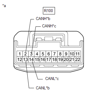
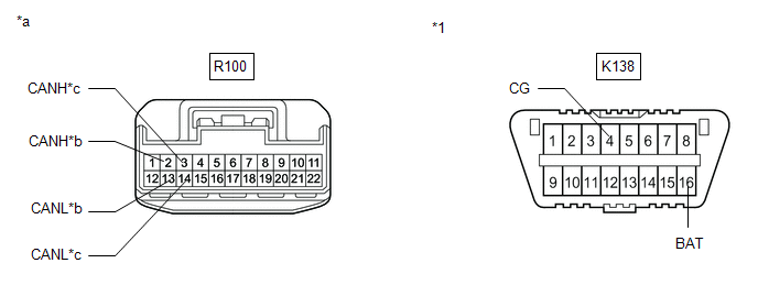
| (a) Disconnect the R100 No. 5 junction connector. |
|
(b) Measure the resistance according to the value(s) in the table below.
Standard Resistance:
|
Tester Connection | Condition |
Specified Condition |
|---|---|---|
|
R100-3 (CANH) - R100-14(CANL) |
Cable disconnected from negative (-) battery terminal |
108 to 132 Ω |
|
R100-2 (CANH) - R100-13(CANL) |
Cable disconnected from negative (-) battery terminal |
108 to 132 Ω |
|
Result | Proceed to |
|---|---|
|
OK | A |
|
NG (to blind spot monitor sensor RH CAN main wire) |
B |
| NG (to blind spot monitor sensor LH CAN main wire) |
C |
| A |
| REPLACE NO. 5 JUNCTION CONNECTOR |
| C |
| GO TO STEP 9 |
|
| 8. |
CHECK FOR OPEN IN CAN BUS MAIN WIRE (BLIND SPOT MONITOR SENSOR RH) |
(a) Reconnect the R100 No. 5 junction connector.
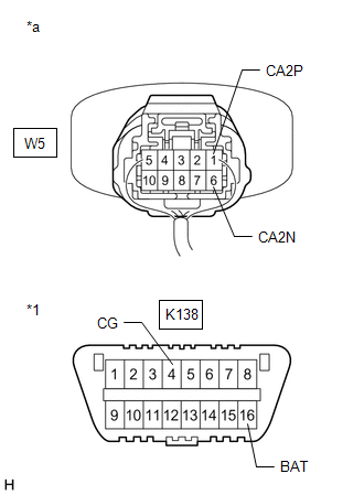
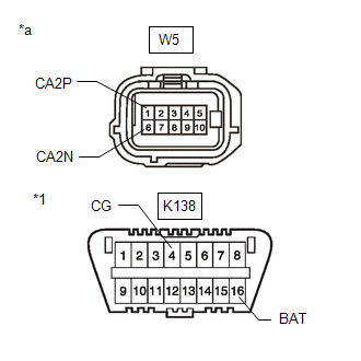
| (b) Disconnect the W5 blind spot monitor sensor RH connector. |
|
(c) Measure the resistance according to the value(s) in the table below.
Standard Resistance:
|
Tester Connection | Condition |
Specified Condition |
|---|---|---|
|
W5-1 (CA2P) - W5-6 (CA2N) |
Cable disconnected from negative (-) battery terminal |
108 to 132 Ω |
| OK | | REPLACE BLIND SPOT MONITOR SENSOR RH |
| NG | | REPAIR OR REPLACE CAN MAIN WIRE OR CONNECTOR (BLIND SPOT MONITOR SENSOR RH - NO. 5 JUNCTION CONNECTOR) |
| 9. |
CHECK FOR OPEN IN CAN BUS MAIN WIRE (BLIND SPOT MONITOR SENSOR LH) |
(a) Reconnect the R100 No. 5 junction connector.
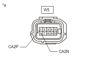
| (b) Disconnect the W6 blind spot monitor sensor LH connector. |
|

(c) Measure the resistance according to the value(s) in the table below.
Standard Resistance:
|
Tester Connection | Condition |
Specified Condition |
|---|---|---|
|
W6-1 (CA2P) - W6-6 (CA2N) |
Cable disconnected from negative (-) battery terminal |
108 to 132 Ω |
| OK | | REPLACE BLIND SPOT MONITOR SENSOR LH |
| NG | | REPAIR OR REPLACE CAN MAIN WIRE OR CONNECTOR (BLIND SPOT MONITOR SENSOR LH - No. 5 JUNCTION CONNECTOR) |
| 10. |
CHECK FOR SHORT IN CAN BUS WIRES (NO. 5 JUNCTION CONNECTOR) |
| (a) Disconnect the R100 No. 5 junction connector. |
|
(b) Measure the resistance according to the value(s) in the table below.
Standard Resistance:
|
Tester Connection | Condition |
Specified Condition |
|---|---|---|
|
R100-3 (CANH) - R100-14 (CANL) |
Cable disconnected from negative (-) battery terminal |
108 to 132 Ω |
|
R100-1 (CANH) - R100-12 (CANL) |
Cable disconnected from negative (-) battery terminal |
108 to 132 Ω |
|
Result | Proceed to |
|---|---|
|
OK | A |
|
NG (to blind spot monitor sensor RH CAN main wire) |
B |
| NG (to blind spot monitor sensor LH CAN main wire) |
C |
| A |
| REPLACE NO. 5 JUNCTION CONNECTOR |
| C |
| GO TO STEP 12 |
|
| 11. |
CHECK FOR SHORT IN CAN BUS WIRES (BLIND SPOT MONITOR SENSOR RH) |
(a) Reconnect the R100 No. 5 junction connector.
| (b) Disconnect the W5 blind spot monitor sensor RH connector. |
|
(c) Measure the resistance according to the value(s) in the table below.
Standard Resistance:
|
Tester Connection | Condition |
Specified Condition |
|---|---|---|
|
W5-1 (CA2P) - W5-6 (CA2N) |
Cable disconnected from negative (-) battery terminal |
108 to 132 Ω |
| OK | | REPLACE BLIND SPOT MONITOR SENSOR RH |
| NG | | REPAIR OR REPLACE CAN MAIN WIRE OR CONNECTOR (BLIND SPOT MONITOR SENSOR RH - NO. 5 JUNCTION CONNECTOR) |
| 12. |
CHECK FOR SHORT IN CAN BUS WIRES (BLIND SPOT MONITOR SENSOR LH) |
(a) Reconnect the R100 No. 5 junction connector.
| (b) Disconnect the W6 blind spot monitor sensor LH connector. |
|
(c) Measure the resistance according to the value(s) in the table below.
Standard Resistance:
|
Tester Connection | Condition |
Specified Condition |
|---|---|---|
|
W6-1 (CA2P) - W6-6 (CA2N) |
Cable disconnected from negative (-) battery terminal |
108 to 132 Ω |
| OK | | REPLACE BLIND SPOT MONITOR SENSOR LH |
| NG | | REPAIR OR REPLACE CAN MAIN WIRE OR CONNECTOR (BLIND SPOT MONITOR SENSOR LH - NO. 5 JUNCTION CONNECTOR) |
| 13. |
CHECK FOR SHORT IN CAN BUS WIRES (NO. 5 JUNCTION CONNECTOR) |
(a) Disconnect the R100 No. 5 junction connector.
(b) Measure the resistance according to the value(s) in the table below.
|
*1 | DLC3 |
- | - |
|
*a | Front view of wire harness connector (to No. 5 Junction Connector) |
*b | to blind spot monitor sensor RH CAN main wire |
|
*c | to blind spot monitor sensor LH CAN main wire |
- | - |
Standard Resistance:
|
Tester Connection | Condition |
Specified Condition |
|---|---|---|
|
R100-3 (CANH) - K138-4 (CG) |
Cable disconnected from negative (-) battery terminal |
200 Ω or higher |
|
R100-14 (CANL) - K138-4 (CG) |
Cable disconnected from negative (-) battery terminal |
200 Ω or higher |
|
R100-3 (CANH) - K138-16 (BAT) |
Cable disconnected from negative (-) battery terminal |
6 kΩ or higher |
|
R100-14 (CANL) - K138-16 (BAT) |
Cable disconnected from negative (-) battery terminal |
6 kΩ or higher |
|
R100-2 (CANH) - K138-4 (CG) |
Cable disconnected from negative (-) battery terminal |
200 Ω or higher |
|
R100-13 (CANL) - K138-4 (CG) |
Cable disconnected from negative (-) battery terminal |
200 Ω or higher |
|
R100-2 (CANH) - K138-16 (BAT) |
Cable disconnected from negative (-) battery terminal |
6 kΩ or higher |
|
R100-13 (CANL) - K138-16 (BAT) |
Cable disconnected from negative (-) battery terminal |
6 kΩ or higher |
|
Result | Proceed to |
|---|---|
|
OK | A |
|
NG (to blind spot monitor sensor RH CAN main wire) |
B |
| NG (to blind spot monitor sensor LH CAN main wire) |
C |
| A |
| REPLACE NO. 5 JUNCTION CONNECTOR |
| C |
| GO TO STEP 15 |
|
| 14. |
CHECK FOR SHORT IN CAN BUS WIRES (BLIND SPOT MONITOR SENSOR RH) |
(a) Reconnect the R100 No. 5 junction connector.
(b) Disconnect the W5 blind spot monitor sensor RH connector.
| (c) Measure the resistance according to the value(s) in the table below. Standard Resistance:
|
|
| OK | | REPLACE BLIND SPOT MONITOR SENSOR RH |
| NG | | REPAIR OR REPLACE CAN MAIN WIRE OR CONNECTOR (BLIND SPOT MONITOR SENSOR RH - NO. 5 JUNCTION CONNECTOR) |
| 15. |
CHECK FOR SHORT IN CAN BUS WIRES (BLIND SPOT MONITOR SENSOR LH) |
(a) Reconnect the R100 No. 5 junction connector.
(b) Disconnect the W6 blind spot monitor sensor LH connector.
| (c) Measure the resistance according to the value(s) in the table below. Standard Resistance:
|
|

| OK | | REPLACE BLIND SPOT MONITOR SENSOR LH |
| NG | | REPAIR OR REPLACE CAN MAIN WIRE OR CONNECTOR (BLIND SPOT MONITOR SENSOR LH - NO. 5 JUNCTION CONNECTOR) |
READ NEXT:
 Lost Communication with Blind Spot Monitor Master Module (U0233)
DESCRIPTION This DTC is stored when the blind spot monitor sensor LH judges that there is a communication problem with the blind spot monitor sensor RH.
DTC No. Detection Item
DTC Detecti
Software Incompatibility with Body Control Module "B" (U1331)
DESCRIPTION This DTC is stored when the destination information of the main body ECU (multiplex network body ECU) does not match that of the blind spot monitor sensors. Blind Spot Monitor Master
Buzzer does not Sound
WIRING DIAGRAM
CAUTION / NOTICE / HINT
NOTICE:
When checking for DTCs, make sure that the blind spot monitor system is turned on.
Inspect the fuses for circuits related to this system be
SEE MORE:
Before driving
Floor mat
Use only floor mats designed specifically for vehicles of the same
model and model year as your vehicle. Fix them securely in place
onto the carpet.
1. Insert the retaining hooks (clips)
into the floor mat eyelets.
2. Turn the upper knob of each
retaining hook (clip) to secure
th
Inspection
INSPECTION PROCEDURE 1. INSPECT FUEL PRESSURE SENSOR (FUEL DELIVERY PIPE WITH SENSOR ASSEMBLY LH)
NOTICE:
Do not remove the fuel pressure sensor from the fuel delivery pipe with sensor assembly LH.
If the fuel pressure sensor is removed, replace the fuel pressure sensor (fuel delivery pip
