Toyota Camry (XV70): On-vehicle Inspection
ON-VEHICLE INSPECTION
CAUTION / NOTICE / HINT
HINT:
- Use the same procedure for the RH side and LH side.
- The following procedure is for the LH side.
PROCEDURE
1. REMOVE REAR WHEEL
Click here
.gif)
2. DISCONNECT NO. 2 PARKING BRAKE WIRE ASSEMBLY
Click here
3. SEPARATE REAR DISC BRAKE CALIPER ASSEMBLY
Click here
4. REMOVE REAR DISC
Click here
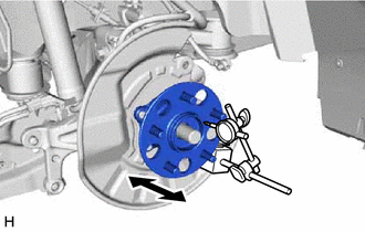
5. INSPECT REAR AXLE HUB BEARING LOOSENESS
| (a) Using a dial indicator with magnetic base, check for looseness near the center of the rear axle hub. Maximum Looseness: 0.05 mm (0.00196 in.) NOTICE:
HINT: If the looseness exceeds the maximum, replace the rear axle hub and bearing assembly. |
|
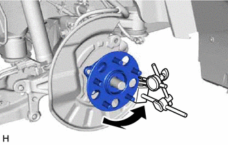
6. INSPECT REAR AXLE HUB RUNOUT
| (a) Using a dial indicator with magnetic base, check for runout on the surface of the rear axle hub outside the rear axle hub bolts. Maximum Runout: 0.05 mm (0.00196 in.) NOTICE:
HINT: If the runout exceeds the maximum, replace the rear axle hub and bearing assembly. |
|
7. INSTALL REAR DISC
Click here
8. INSTALL REAR DISC BRAKE CALIPER ASSEMBLY
Click here
9. CONNECT NO. 2 PARKING BRAKE WIRE ASSEMBLY
Click here
10. INSTALL REAR WHEEL
Click here
READ NEXT:
 Removal
REMOVAL CAUTION / NOTICE / HINT
HINT:
Use the same procedure for the RH side and LH side.
The following procedure is for the LH side.
PROCEDURE 1. REMOVE REAR WHEEL Click here
2. REM
Installation
INSTALLATION CAUTION / NOTICE / HINT
HINT:
Use the same procedure for the RH side and LH side.
The following procedure is for the LH side.
PROCEDURE 1. INSTALL REAR AXLE HUB AND BEARING
Rear Axle Hub Bolt(w/ Electric Parking Brake System)
ComponentsCOMPONENTS ILLUSTRATION
*1 NO. 2 PARKING BRAKE WIRE ASSEMBLY
*2 REAR AXLE HUB BOLT
*3 REAR DISC
*4 REAR DISC BRAKE CALIPER ASSEMBLY
*5 REAR FL
SEE MORE:
Pressure Control Solenoid "D" Circuit Short to Ground or Open (P271314)
DESCRIPTION Refer to DTC P27137F. Click here
DTC No. Detection Item
DTC Detection Condition Trouble Area
MIL Memory
Note P271314
Pressure Control Solenoid "D" Circuit Short to Ground or Open
While the engine is running, a short to ground or open is det
Removal
REMOVAL CAUTION / NOTICE / HINT
The necessary procedures (adjustment, calibration, initialization, or registration) that must be performed after parts are removed and installed, or replaced during spark plug removal/installation are shown below. Necessary Procedures After Parts Removed/Installed/R
