Toyota Camry (XV70): Parts Location
PARTS LOCATION
ILLUSTRATION
|
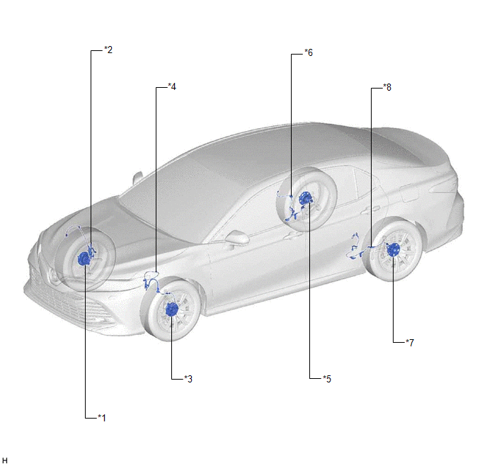
*1 | FRONT AXLE HUB SUB-ASSEMBLY RH - FRONT SPEED SENSOR ROTOR RH |
*2 | FRONT SPEED SENSOR RH |
|
*3 | FRONT AXLE HUB SUB-ASSEMBLY LH - FRONT SPEED SENSOR ROTOR LH |
*4 | FRONT SPEED SENSOR LH |
|
*5 | REAR AXLE HUB AND BEARING ASSEMBLY RH - REAR SPEED SENSOR RH - REAR SPEED SENSOR ROTOR RH |
*6 | SKID CONTROL SENSOR WIRE RH |
|
*7 | REAR AXLE HUB AND BEARING ASSEMBLY LH - REAR SPEED SENSOR LH - REAR SPEED SENSOR ROTOR LH |
*8 | SKID CONTROL SENSOR WIRE LH |
ILLUSTRATION

|
*1 | VACUUM WARNING SWITCH ASSEMBLY |
*2 | BRAKE MASTER CYLINDER RESERVOIR ASSEMBLY - BRAKE FLUID LEVEL WARNING SWITCH |
|
*3 | ECM |
*4 | ENGINE ROOM RELAY BLOCK AND JUNCTION BLOCK ASSEMBLY - ABS NO. 1 FUSE - ABS NO. 2 FUSE |
|
*5 | BRAKE ACTUATOR ASSEMBLY - SKID CONTROL ECU | *6 |
RACK AND PINION POWER STEERING GEAR ASSEMBLY - POWER STEERING ECU |
ILLUSTRATION
|
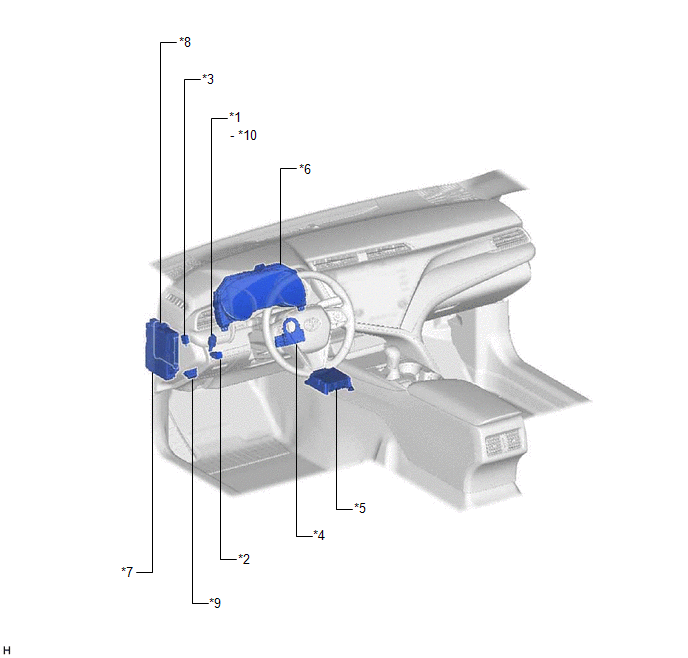
*1 | STOP LIGHT SWITCH ASSEMBLY |
*2 | VSC OFF SWITCH |
|
*3 | PARKING BRAKE SWITCH ASSEMBLY |
*4 | STEERING ANGLE SENSOR |
|
*5 | AIRBAG SENSOR ASSEMBLY - YAW RATE AND ACCELERATION SENSOR |
*6 | COMBINATION METER ASSEMBLY - ABS WARNING LIGHT - BRAKE SYSTEM WARNING LIGHT (RED INDICATOR) - MULTI-INFORMATION DISPLAY (TRACTION CONTROL TURNED OFF) - VSC OFF INDICATOR LIGHT - SLIP INDICATOR LIGHT |
|
*7 | INSTRUMENT PANEL JUNCTION BLOCK ASSEMBLY - ECU-IG1 NO. 2 FUSE - ECU-DCC NO. 1 FUSE - A/BAG-IG2 FUSE - STOP FUSE | *8 |
MAIN BODY ECU (MULTIPLEX NETWORK BODY ECU) |
|
*9 | DLC3 |
*10 | STOP LIGHT CONTROL RELAY |
READ NEXT:
 System Diagram
SYSTEM DIAGRAM
Transmitting ECU (Transmitter)
Receiving ECU Signal
Communication Method
Skid control ECU (brake actuator assembly)
Steering angle sensor
How To Proceed With Troubleshooting
CAUTION / NOTICE / HINT HINT: *: Use the Techstream. PROCEDURE
1.
VEHICLE BROUGHT TO WORKSHOP
NEXT
2.
CUSTOMER PROBLEM ANALYSIS (a) Interview
Check For Intermittent Problems
CHECK FOR INTERMITTENT PROBLEMS CHECK FOR INTERMITTENT PROBLEMS
HINT: A momentary interruption (open circuit) in the connectors and/or wire harness between the sensors and ECUs can be detected using
SEE MORE:
Automatic air conditioning
system (with "SYNC"
button)
Air outlets and fan speed are automatically adjusted according
to the temperature setting.
Air conditioning controls
■ Adjusting the temperature setting
To adjust the temperature setting, turn
clockwise to increase
the temperature and counterclockwise to decrease the temperature.
If i
Cleaning and protecting
the vehicle interior
The following procedures will help protect your vehicle's interior
and keep it in top condition:
Protecting the vehicle interior
Remove dirt and dust using a vacuum cleaner. Wipe dirty surfaces
with a cloth dampened with lukewarm water.
If dirt cannot be removed, wipe it off with a soft cl
