Toyota Camry (XV70): Reassembly
REASSEMBLY
CAUTION / NOTICE / HINT
NOTICE:
- As imbalance affects vibration and noise performance, make sure to ensure correct angular alignment of the following components during installation.
- PROPELLER INTERMEDIATE SHAFT ASSEMBLY
- REAR PROPELLER SHAFT ASSEMBLY
- LARGE DIAMETER PROPELLER SHAFT BOOT CLAMP
- SMALL DIAMETER PROPELLER SHAFT BOOT CLAMP
- BALL CAGE, INNER RACE
- When using a vise, place aluminum plates between the part and vise.
- When using a vise, do not overtighten it.
PROCEDURE
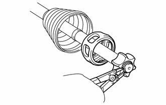
1. INSTALL CENTER SUPPORT BEARING
| (a) Using SST and a plastic hammer, install a new No. 1 dust deflector to the dimension (A). SST: 09710-18050 09711-01090 Dimension (A): 17.2 to 17.6 mm (0.678 to 0.692 in.) NOTICE: Do not excessively press the No. 1 dust deflector. |
|
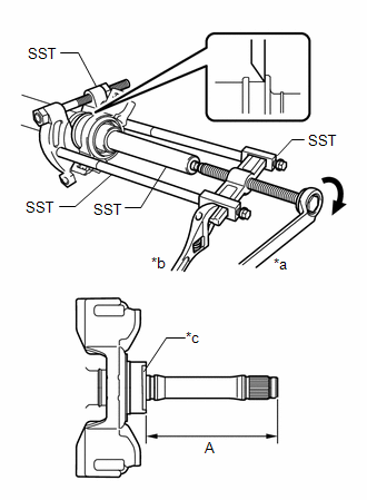
| (b) Using SST, install a new center support bearing and flange to the propeller intermediate shaft assembly to the dimension (A). SST: 09612-22011 SST: 09950-00020 SST: 09950-00040 SST: 09950-40011 09951-04020 09952-04010 09953-04020 09954-04040 09957-04010 Dimension (A): 113.5 mm (4.47 in.) HINT: Perform this procedure with 2 or more people and prevent the propeller shaft from rotating. |
|
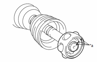
2. INSTALL UNIVERSAL BOOT KIT
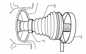
| (a) Install each new parts to the propeller intermediate shaft assembly in the order shown in the illustration. |
|
(b) Install the small diameter side of the propeller shaft boot to the propeller intermediate shaft assembly.
| (c) Align the matchmarks placed before removal. |
|
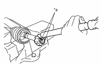
(d) Using a brass bar and a hammer, install the inner race to the propeller intermediate shaft assembly.
NOTICE:
Be careful not to damage the inner race.
| (e) Using a snap ring expander, install a new propeller shaft snap ring to the propeller intermediate shaft assembly. |
|
| (f) Align the matchmarks and install the ball cage to the inner race. |
|
(g) Install the 6 balls with grease to the inner race.
NOTICE:
Be careful not to drop the balls.
HINT:
Apply grease to the balls to keep them from falling.
3. INSTALL REAR PROPELLER SHAFT ASSEMBLY
| (a) Align the matchmarks and insert the propeller intermediate shaft assembly into the rear propeller shaft assembly. |
|
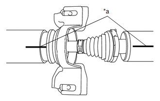
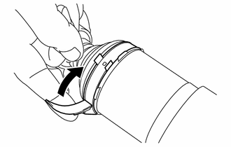
| (b) Align the crimp position of the small diameter propeller shaft boot clamp with the matchmark of the rear propeller shaft assembly. |
|
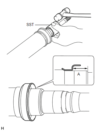
| (c) Place SST onto the small diameter propeller shaft boot clamp, and while pushing it against the propeller shaft boot, slightly tighten the bolt of SST. SST: 09521-24010 |
|
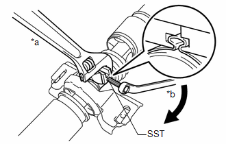
(d) While holding SST, tighten the bolt of SST until the specified clearance value of the small diameter propeller shaft boot clamp is met.
Clearance:
Below 0.8 mm (0.0315 in.)
(e) Remove SST.
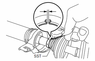
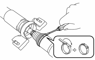
| (f) Using SST, measure the clearance shown in the illustration. SST: 09240-00021 Clearance: Below 0.8 mm (0.0315 in.) NOTICE: If the clearance is not as specified, retighten SST. |
|
(g) Fill the rear propeller shaft assembly and propeller shaft boot with grease.
Standard Grease Capacity:
90 to 100 g (3.18 to 3.52 oz)
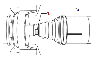
| (h) Install the propeller shaft boot to the rear propeller shaft assembly to the specified value (A). |
|
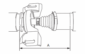
(i) Measure the distance (A) of the propeller shaft assembly shown in the illustration. If the value is not as specified, reinstall the propeller shaft boot.
Dimension (A):
189.3 to 191.7 mm (7.45 to 7.55 in.)
| (j) Align the crimp position of the large diameter propeller shaft boot clamp with the matchmark of the rear propeller shaft assembly. |
|
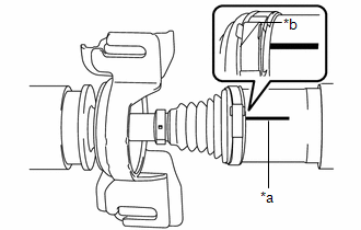
| (k) Temporarily bend the lever from the fulcrum part of the large diameter propeller shaft boot clamp. |
|
| (l) Using a screwdriver, stake the large diameter propeller shaft boot clamp. NOTICE: Be careful not to damage the propeller shaft boot. |
|
| (m) Confirm that the matchmarks of the propeller intermediate shaft assembly and rear propeller shaft assembly are aligned. |
|
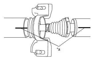
| (n) Check whether the propeller intermediate shaft assembly dimension (A) is within specification. Dimension (A): 189.3 to 191.7 mm (7.45 to 7.55 in.) |
|
READ NEXT:
 Installation
INSTALLATION PROCEDURE 1. TEMPORARILY TIGHTEN PROPELLER WITH CENTER BEARING SHAFT ASSEMBLY
(a) When reusing a propeller with center bearing shaft assembly and rear differential carrier assembly:
Propeller Shaft System
Problem Symptoms TablePROBLEM SYMPTOMS TABLE
HINT: Use the table below to help determine the cause of problem symptoms. If multiple suspected areas are listed, the potential causes of the symptoms a
SEE MORE:
Fail-safe Chart
FAIL-SAFE CHART FAIL-SAFE CHART Dynamic Torque Control AWD System
DTC No. Trouble Area
AWD Warning Message Fail-safe Operation
Memory Fail-safe Deactivation Condition
C120C Linear Solenoid Power Supply System Malfunction
Displayed Prohibited
Yes Igniti
Reverse Signal Circuit
DESCRIPTION The radio and display receiver assembly receives a reverse signal from the BKUP LP relay. WIRING DIAGRAM
PROCEDURE
1.
CHECK BACK-UP LIGHT (a) Move the shift lever to R and check if the back-up lights come on.
OK: The back-up lights come on.
NG
GO TO LIGHTIN
