Toyota Camry (XV70): Installation
INSTALLATION
PROCEDURE
1. TEMPORARILY TIGHTEN PROPELLER WITH CENTER BEARING SHAFT ASSEMBLY
| (a) When reusing a propeller with center bearing shaft assembly and rear differential carrier assembly: (1) Align the matchmarks on the rear differential carrier assembly and propeller with center bearing shaft assembly. (2) Temporarily install the 4 nuts and 4 washers. NOTICE: Do not apply grease to the 4 bolts, 4 nuts or 4 washers. |
|
.png)
| (b) When using a new propeller with center bearing shaft assembly or rear differential carrier assembly: (1) Align the alignment marks on the rear differential carrier assembly and propeller with center bearing shaft assembly. (2) Temporarily install the 4 nuts and 4 washers. NOTICE: Do not apply grease to the 4 bolts, 4 nuts or 4 washers. |
|
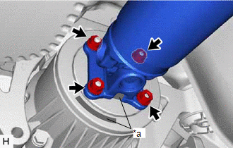
| (c) Align the matchmarks on the transfer assembly and propeller with center bearing shaft assembly. |
|
.png)
(d) Temporarily install the 4 nuts and 4 washers.
NOTICE:
Do not apply grease to the 4 bolts, 4 nuts or 4 washers.
| (e) Temporarily install the propeller with center bearing shaft assembly with the 2 bolts and 2 center No. 2 support bearing washers (for front side). NOTICE:
|
|
.png)
| (f) Temporarily install the propeller with center bearing shaft assembly with the 2 bolts and 2 center No. 2 support bearing washers (for rear side). NOTICE:
|
|
.png)
| (g) Fully tighten the 4 nuts. Torque: 35 N |
READ NEXT:
 Propeller Shaft System
Problem Symptoms TablePROBLEM SYMPTOMS TABLE
HINT: Use the table below to help determine the cause of problem symptoms. If multiple suspected areas are listed, the potential causes of the symptoms a
Components
COMPONENTS ILLUSTRATION
*1 REAR DRIVE SHAFT ASSEMBLY LH
*2 REAR DRIVE SHAFT INBOARD JOINT SHAFT SNAP RING LH
*3 REAR DIFFERENTIAL CARRIER ASSEMBLY
- -
SEE MORE:
Removal
REMOVAL PROCEDURE 1. REMOVE FRONT WHEEL OPENING EXTENSION PAD RH
Click here
2. REMOVE FRONT WHEEL OPENING EXTENSION PAD LH Click here
3. REMOVE NO. 1 ENGINE UNDER COVER
Click here
4. REMOVE NO. 2 ENGINE UNDER COVER ASSEMBLY Click here
Reverse Signal Circuit
DESCRIPTION The radio and display receiver assembly receives a reverse signal from the BKUP LP relay. WIRING DIAGRAM
PROCEDURE
1.
CHECK BACK-UP LIGHT (a) Move the shift lever to R and check if the back-up lights come on.
OK: The back-up lights come on.
NG
GO TO LIGHTIN
