Toyota Camry (XV70): Removal
REMOVAL
CAUTION / NOTICE / HINT
The necessary procedures (adjustment, calibration, initialization, or registration) that must be performed after parts are removed and installed, or replaced during stereo component amplifier assembly removal/installation are shown below.
Necessary Procedure After Parts Removed/Installed/Replaced|
Replaced Part or Performed Procedure |
Necessary Procedures | Effect/Inoperative Function when Necessary Procedure not Performed |
Link |
|---|---|---|---|
| Disconnect cable from negative battery terminal |
Perform steering sensor zero point calibration |
Lane Tracing Assist System |
|
|
Pre-collision System | |||
|
Memorize steering angle neutral point |
Parking Assist Monitor System |
| |
|
Panoramic View Monitor System |
|
CAUTION:
Some of these service operations affect the SRS airbag system. Read the precautionary notices concerning the SRS airbag system before servicing.
Click here .gif)
.png)
PROCEDURE
1. REMOVE FRONT SEAT ASSEMBLY LH
Click here
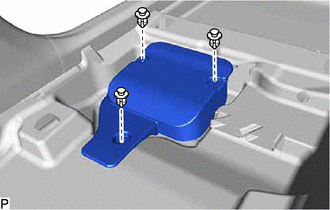
2. REMOVE AUDIO AMPLIFIER COVER
| (a) Remove the 3 clips and audio amplifier cover. |
|
3. REMOVE STEREO COMPONENT AMPLIFIER ASSEMBLY WITH BRACKET
| (a) Disconnect each connector. |
|
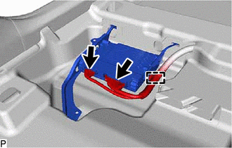
(b) Disengage the clamp.
|
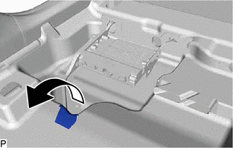
(c) Turn back the front floor carpet assembly and front floor mat as shown in the illustration. |
|
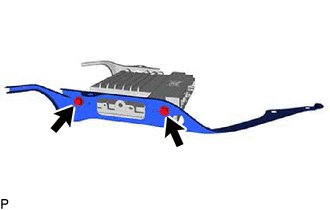
| (d) Remove the bolt. |
|
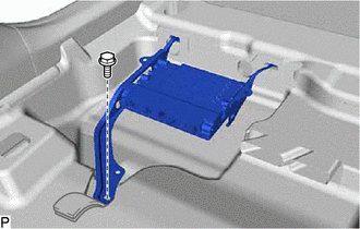
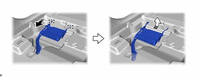
(e) Disengage the 2 guides and remove the stereo component amplifier assembly with bracket as shown in the illustration.
.png) |
Remove in this Direction (1) |
.png) |
Remove in this Direction (2) |
4. REMOVE NO. 1 AMPLIFIER BRACKET
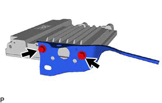
| (a) Remove the 2 screws and No. 1 amplifier bracket. |
|
5. REMOVE NO. 2 AMPLIFIER BRACKET
| (a) Remove the 2 screws and No. 2 amplifier bracket. |
|
6. REMOVE STEREO COMPONENT AMPLIFIER ASSEMBLY
READ NEXT:
 Installation
INSTALLATION PROCEDURE 1. INSTALL STEREO COMPONENT AMPLIFIER ASSEMBLY
2. INSTALL NO. 2 AMPLIFIER BRACKET (a) Install the No. 2 amplifier bracket with the 2 screws.
3. INSTALL NO. 1 AMPLIFIER BRACK
Stereo Jack Adapter Assembly
ComponentsCOMPONENTS ILLUSTRATION
*1 LOWER CENTER INSTRUMENT PANEL FINISH PANEL
*2 NO. 1 METER HOOD CLUSTER
*3 NO. 1 STEREO JACK ADAPTER ASSEMBLY
- - RemovalRE
SEE MORE:
Parking Brake Switch
ComponentsCOMPONENTS ILLUSTRATION
*1 PARKING BRAKE PEDAL ASSEMBLY
*2 PARKING BRAKE SWITCH ASSEMBLY
N*m (kgf*cm, ft.*lbf): Specified torque
- - RemovalREMOVAL CAUTION / NOTICE / HINT
The necessary procedures (adjustment, calibration, initialization, or
Lost Communication with Blind Spot Monitor Slave Module (U0232)
DESCRIPTION This DTC is stored when the blind spot monitor sensor RH judges that there is a communication problem with the blind spot monitor sensor LH.
DTC No. Detection Item
DTC Detection Condition Trouble Area
U0232 Lost Communication with Blind Spot Monitor Slave Module
