Toyota Camry (XV70): Removal
REMOVAL
CAUTION / NOTICE / HINT
NOTICE:
- Immediately after installing the brake pads, the braking performance may be reduced. Always perform a road test in a safe place while paying attention to the surroundings.
- After replacing the rear disc brake pads, always perform a road test to check the braking performance and check for vibrations.
HINT:
- Use the same procedure for the RH side and LH side.
- The following procedure is for the LH side.
PROCEDURE
1. REMOVE REAR WHEEL
Click here
.gif)
2. DRAIN BRAKE FLUID
NOTICE:
If brake fluid leaks onto any painted surface, immediately wash it off.
3. DISCONNECT REAR FLEXIBLE HOSE
| (a) Remove the union bolt and gasket, and disconnect the rear flexible hose from the rear disc brake cylinder assembly. |
|

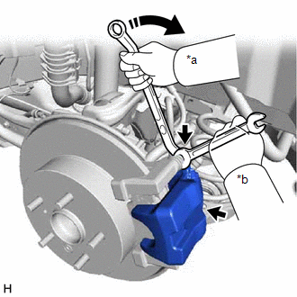
4. REMOVE REAR DISC BRAKE CYLINDER ASSEMBLY
| (a) Hold the 2 rear disc brake cylinder slide pins and remove the 2 bolts and rear disc brake cylinder assembly from the rear disc brake cylinder mounting. |
|
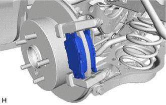
5. REMOVE REAR DISC BRAKE PAD
| (a) Remove the 2 rear disc brake pads from the rear disc brake cylinder mounting. |
|
6. REMOVE REAR DISC BRAKE ANTI-SQUEAL SHIM KIT
Click here
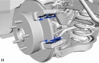
7. REMOVE REAR DISC BRAKE PAD SUPPORT PLATE
NOTICE:
- If the rear disc brake pad support plate is securely installed, do not remove the rear disc brake pad support plate from the rear disc brake cylinder mounting as it can be reused.
- As the rear disc brake pad support plate is a non-reusable part, if the rear disc brake pad support plate is removed from the rear disc brake cylinder mounting, it must be replaced with a new one.
- If the rear disc brake pad support plate is loose or deformed after being installed to the rear disc brake cylinder mounting, replace it with a new one.
| (a) Remove the 2 rear disc brake pad support plates from the rear disc brake cylinder mounting. |
|
8. REMOVE REAR DISC BRAKE CYLINDER SLIDE PIN (for Upper Side)
| (a) Remove the rear disc brake cylinder slide pin from the rear disc brake cylinder mounting. |
|
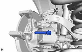
9. REMOVE REAR DISC BRAKE CYLINDER SLIDE PIN (for Lower Side)
| (a) Remove the rear disc brake cylinder slide pin from the rear disc brake cylinder mounting. |
|
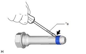
| (b) Using a screwdriver with its tip wrapped with protective tape, remove the rear disc brake cylinder slide bushing from the rear disc brake cylinder slide pin. NOTICE: Do not damage the rear disc brake cylinder slide pin. |
|
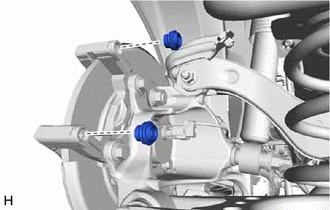
10. REMOVE REAR DISC BRAKE BUSHING DUST BOOT
| (a) Remove the 2 rear disc brake bushing dust boots from the rear disc brake cylinder mounting. |
|
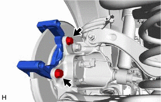
11. REMOVE REAR DISC BRAKE CYLINDER MOUNTING
| (a) Remove the 2 bolts and rear disc brake cylinder mounting from the rear axle carrier sub-assembly. |
|
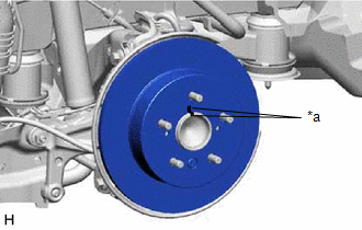
12. REMOVE PARKING BRAKE SHOE ADJUSTING HOLE PLUG
(a) Remove the parking brake shoe adjusting hole plug from the rear disc.
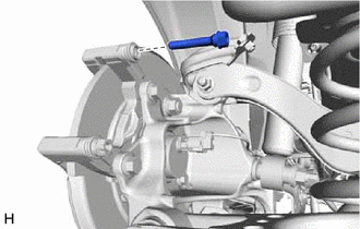
13. REMOVE REAR DISC
| (a) Put matchmarks on the rear disc and the rear axle hub and bearing assembly. |
|
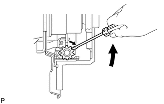
| (b) Release the parking brake and remove the rear disc. HINT: If the disc cannot be removed easily, use a screwdriver to turn the shoe adjuster as shown in the illustration in order to contract the parking brake shoes. |
|
READ NEXT:
 Disassembly
DISASSEMBLY PROCEDURE 1. REMOVE CYLINDER BOOT
(a) Using a screwdriver with its tip wrapped with protective tape, remove the rear disc brake piston set ring and cylinder boot from the rear disc b
Inspection
INSPECTION PROCEDURE 1. INSPECT BRAKE CYLINDER AND PISTON
(a) Check the rear disc brake cylinder bore and rear disc brake piston for rust and scoring. If necessary, replace the rear disc brake cylin
Reassembly
REASSEMBLY PROCEDURE 1. TEMPORARILY TIGHTEN REAR DISC BRAKE BLEEDER PLUG
(a) Temporarily install the rear disc brake bleeder plug to the rear disc brake cylinder.
HINT: Fully tighten the rear disc
SEE MORE:
Throttle/Pedal Position Sensor "A" Minimum Stop Performance (P210900)
DESCRIPTION The idle speed is controlled by the Electronic Throttle Control System (ETCS). The ETCS is comprised of a throttle actuator, which operates the throttle valve, and a throttle position sensor, which detects the opening amount of the throttle valve. The ECM controls the throttle actuator t
Installation
INSTALLATION CAUTION / NOTICE / HINT
HINT:
Use the same procedure for the RH side and LH side.
The following procedure is for the LH side.
PROCEDURE 1. TEMPORARILY INSTALL REAR AXLE CARRIER SUB-ASSEMBLY
(a) Temporarily install the rear axle carrier sub-assembly to the rear shock abso
