Toyota Camry (XV70): Removal
REMOVAL
CAUTION / NOTICE / HINT
The necessary procedures (adjustment, calibration, initialization, or registration) that must be performed after parts are removed and installed, or replaced during rear drive shaft assembly removal/installation are shown below.
Necessary Procedures After Parts Removed/Installed/Replaced|
Replaced Part or Performed Procedure |
Necessary Procedure | Effect/Inoperative Function when Necessary Procedure not Performed |
Link |
|---|---|---|---|
| Rear wheel alignment adjustment |
|
|
|
|
Suspension, tires, etc. (The vehicle height changes because of suspension or tire replacement) |
Rear television camera assembly optical axis (Back camera position setting) |
Parking assist monitor system |
|
| Panoramic view monitor system |
|
HINT:
- Use the same procedure for the RH side and LH side.
- The following procedure is for the LH side.
PROCEDURE
1. REMOVE REAR WHEEL
Click here
.gif)
2. REMOVE REAR AXLE CARRIER
Click here
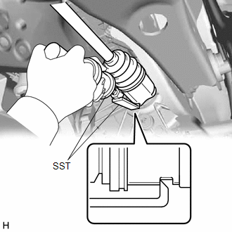
3. REMOVE REAR DRIVE SHAFT ASSEMBLY LH
| (a) Using SST, remove the rear drive shaft assembly LH from the rear differential carrier assembly. SST: 09520-01011 SST: 09520-20010 09521-02010 09521-02040 09521-02060 NOTICE:
|
|
4. REMOVE REAR DRIVE SHAFT INBOARD JOINT SHAFT SNAP RING LH
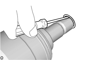
(a) Using a screwdriver, remove the rear drive shaft inboard joint shaft snap ring LH.
READ NEXT:
 Disassembly
DISASSEMBLY CAUTION / NOTICE / HINT
NOTICE:
When using a vise, place aluminum plates between the part and vise.
When using a vise, do not overtighten it.
HINT:
Use the same procedur
Inspection
INSPECTION CAUTION / NOTICE / HINT
NOTICE:
When using a vise, place aluminum plates between the part and vise.
When using a vise, do not overtighten it.
PROCEDURE 1. INSPECT REAR DRIVE S
Reassembly
REASSEMBLY CAUTION / NOTICE / HINT
NOTICE:
When using a vise, place aluminum plates between the part and vise.
When using a vise, do not overtighten it.
HINT:
Use the same procedure
SEE MORE:
VEHICLE CONTROL HISTORY (RoB)
VEHICLE CONTROL HISTORY (RoB) DESCRIPTION
Vehicle Control History (RoB) is a function that captures and stores ECU data when triggered by specific vehicle behavior.
It may be possible to determine the cause of the malfunction by checking the vehicle history information and freeze frame dat
Inspection
INSPECTION PROCEDURE 1. INSPECT AND ADJUST BRAKE BOOSTER PUSH ROD
NOTICE: Make the adjustment with no vacuum in the brake booster assembly. (Depress the brake pedal several times with the engine stopped.)
HINT:
Adjustment of the brake booster push rod is required when the brake master cylind
