Toyota Camry (XV70): Replacement
REPLACEMENT
CAUTION / NOTICE / HINT
The necessary procedures (adjustment, calibration, initialization or registration) that must be performed after parts are removed and installed, or replaced during transfer case oil seal removal/installation are shown below.
Necessary Procedures After Parts Removed/Installed/Replaced|
Replaced Part or Performed Procedure |
Necessary Procedure | Effect/Inoperative Function when Necessary Procedure not Performed |
Link |
|---|---|---|---|
|
*1: w/ Smart Key System
*2: w/o Smart Key System *3: When the ECM is replaced with a new one, reset memory is unnecessary. *4: The vehicle height changes because of suspension or tire replacement. *5: w/ Electric Parking Brake System *6: w/o Electric Parking Brake System | |||
|
Battery terminal is disconnected/reconnected |
Perform steering sensor zero point calibration |
Lane Tracing Assist System |
|
|
Pre-collision system | |||
|
Memorize steering angle neutral point |
Parking assist monitor system |
| |
|
Panoramic view monitor system |
| ||
|
Replacement of ECM | Vehicle Identification Number (VIN) registration |
MIL comes on |
|
|
ECU communication ID registration (Immobiliser system) |
Engine start function |
| |
| Inspection after repair |
|
|
|
Replacement of automatic transaxle assembly |
|
|
|
|
Replacement of ECM (If possible, read the transaxle compensation code from the previous ECM) |
| ||
| Replacement of ECM (If impossible, read the transaxle compensation code from the previous ECM) |
| ||
| Replacement of automatic transaxle fluid |
ATF thermal degradation estimate reset |
The value of the Data List item "ATF Thermal Degradation Estimate" is not estimated correctly. |
|
|
Front wheel alignment adjustment |
|
|
|
|
|
|
|
|
Suspension, tires, etc.*4 |
Rear television camera assembly optical axis (Back camera position setting) |
Parking assist monitor system |
|
|
Replacement of front bumper assembly |
Front television camera view adjustment |
Panoramic view monitor system |
|
|
Suspension, tires, etc.*4 |
| ||
| Replacement of ECM*1 |
Code registration (Smart key System (for Start Function)) |
|
|
|
Replacement of ECM*2 | Code registration (Immobiliser system (w/o Smart Key System)) |
|
|
CAUTION:
- The engine assembly with transaxle is very heavy. Be sure to follow the procedure described in the repair manual, or the engine lifter may suddenly drop or the engine assembly with transaxle may fall off the engine lifter.
.png)
*a
An Object Exceeding Weight Limit of Engine Lifter
- To prevent burns, do not touch the engine, exhaust manifold or other high temperature components while the engine is hot.
.png)
- The automatic transaxle assembly is very heavy. Be sure to follow the procedure described in the repair manual, or the transmission jack may suddenly drop.
.png)
*a
An Object Exceeding Weight Limit of Transmission Jack
NOTICE:
- After the ignition switch is turned off, the radio and display receiver assembly records various types of memory and settings. As a result, after turning the ignition switch off, make sure to wait at least 85 seconds before disconnecting the cable from the negative (-) battery terminal. (for Audio and Visual System)
- After the engine switch is turned off, the radio and display receiver assembly records various types of memory and settings. As a result, after turning the engine switch off, make sure to wait at least 85 seconds before disconnecting the cable from the negative (-) battery terminal. (for Navigation System)
PROCEDURE
1. REMOVE TRANSFER ASSEMBLY
Click here
.gif)
2. REMOVE TRANSFER AND TRANSAXLE SETTING STUD BOLT
Click here
3. SECURE TRANSFER ASSEMBLY
Click here
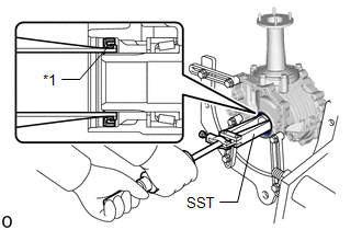
4. REMOVE TRANSFER CASE OIL SEAL
| (a) Using SST, remove the transfer case oil seal from the transfer assembly. SST: 09308-00010 NOTICE:
|
|
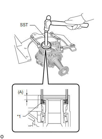
5. INSTALL TRANSFER CASE OIL SEAL
(a) Coat the lip of a new transfer case oil seal with MP grease.
| (b) Using SST and a hammer, tap in the transfer case oil seal to the transfer assembly as shown in the illustration. SST: 09608-10010 SST: 09950-70010 09951-07100 Drive in depth (A): 9.5 to 10.5 mm (0.375 to 0.413 in.) NOTICE:
|
|
6. REMOVE TRANSFER ASSEMBLY
Click here
7. INSTALL TRANSFER AND TRANSAXLE SETTING STUD BOLT
Click here
8. INSTALL TRANSFER ASSEMBLY
Click here
READ NEXT:
 Components
COMPONENTS ILLUSTRATION
*1 FRONT WHEEL OPENING EXTENSION PAD RH
*2 FRONT WHEEL OPENING EXTENSION PAD LH
*3 NO. 1 ENGINE UNDER COVER
*4 NO. 2 ENGINE UNDER COVER AS
Replacement
REPLACEMENT CAUTION / NOTICE / HINT
The necessary procedures (adjustment, calibration, initialization or registration) that must be performed after parts are removed and installed, or replaced durin
SEE MORE:
Transmission Range Sensor "A" Circuit Open (P070513,P070562)
DESCRIPTION The park/neutral position switch assembly detects the shift lever position and sends signals to the ECM.
DTC No. Detection Item
DTC Detection Condition Trouble Area
MIL Memory
Note P070513
Transmission Range Sensor "A" Circuit Open
When the engi
Inspection
INSPECTION PROCEDURE 1. INSPECT VSC OFF SWITCH
(a) Make sure that there is no looseness at the locking part and the connecting part of the connector.
OK: The connector is securely connected.
*a Component without harness connected
(VSC OFF switch)
