Toyota Camry (XV70): System Diagram
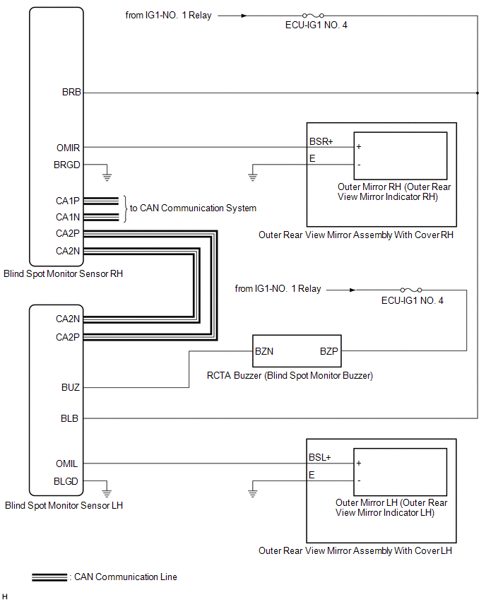
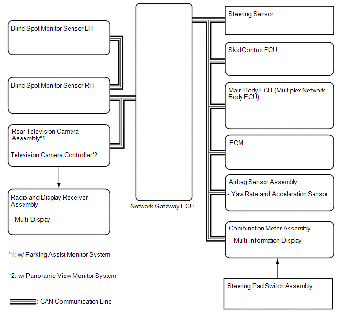
SYSTEM DIAGRAM
READ NEXT:
 System Description
SYSTEM DESCRIPTION OPERATION OF OUTER REAR VIEW MIRROR INDICATOR AND RCTA BUZZER (BLIND SPOT MONITOR BUZZER)
(a) Initial check (1) When the blind spot monitor system is turned on with the engine swi
How To Proceed With Troubleshooting
CAUTION / NOTICE / HINT
HINT:
Use the following procedure to troubleshoot the blind spot monitor system.
*: Use the Techstream.
PROCEDURE
1. VEHICLE BROUGHT TO WORKSHOP
Operation Check
OPERATION CHECK PERFORM BLIND SPOT MONITOR BEAM AXIS CONFIRMATION
HINT: The blind spot monitor beam axis confirmation is performed to confirm whether the sensor beam axis is correct, and to adjust t
SEE MORE:
GNSS Antenna Circuit Short to Ground (B15C111,B15C113)
DESCRIPTION These DTCs are stored when a malfunction occurs in the telephone and GPS antenna (for Roof Side) circuit.
DTC No. Detection Item
DTC Detection Condition Trouble Area
B15C111 GNSS Antenna Circuit Short to Ground
Current to the GNSS antenna is lower than the
Removal
REMOVAL CAUTION / NOTICE / HINT
The necessary procedures (adjustment, calibration, initialization, or registration) that must be performed after parts are removed and installed, or replaced during rear axle carrier sub-assembly removal/installation are shown below. Necessary Procedures After Parts
© 2023-2025 Copyright www.tocamry.com
