Toyota Camry (XV70): Telematics Transceiver Disconnected (B15DB)
DESCRIPTION
If the radio and display receiver assembly cannot detect the DCM (telematics transceiver) for a certain period of time (90 seconds) after the engine switch is turned on (ACC) and the radio and display receiver assembly confirms that the information is missing by checking past DCM (telematics transceiver) recognition information (registered information), this DTC will be stored.
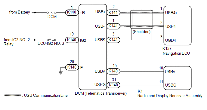
The telematics system uses USB communication between devices. If an open, short, short to +B or short to ground occurs in the USB circuit, communication is interrupted and the telematics system will not operate normally.
|
DTC No. | Detection Item |
DTC Detection Condition | Trouble Area |
|---|---|---|---|
|
B15DB | Telematics Transceiver Disconnected |
DCM (telematics transceiver) disconnected |
|
HINT:
This DTC may be stored due to environmental reasons such as electrical noise or interference.
WIRING DIAGRAM
CAUTION / NOTICE / HINT
NOTICE:
- Depending on the parts that are replaced during vehicle inspection or maintenance, performing initialization, registration or calibration may be needed. Refer to Precaution for Navigation System.
Click here
.gif)
- When replacing the radio and display receiver assembly or navigation ECU, always replace it with a new one. If a radio and display receiver assembly or navigation ECU which was installed to another vehicle is used, the following may occur:
- A communication malfunction DTC may be stored.
- The radio and display receiver assembly or navigation ECU may not operate normally.
- Inspect the fuses for circuits related to this system before performing the following procedure.
- Before replacing the DCM (telematics transceiver), refer to Registration.
Click here
PROCEDURE
|
1. | CHECK DTC |
(a) Clear the DTCs.
Body Electrical > Navigation System > Clear DTCs(b) Turn the engine switch off.
(c) Turn the engine switch on (IG) and wait for 90 seconds.
(d) Recheck for DTCs and check that no DTCs are output.
Body Electrical > Navigation System > Trouble CodesOK:
No DTCs are output.
| OK | .gif) |
USE SIMULATION METHOD TO CHECK |
|
.gif)
| 2. |
CHECK HARNESS AND CONNECTOR (DCM (TELEMATICS TRANSCEIVER) POWER SOURCE) |
(a) Disconnect the K140 DCM (telematics transceiver) connector.
(b) Measure the resistance according to the value(s) in the table below.
Standard Resistance:
|
Tester Connection | Condition |
Specified Condition |
|---|---|---|
|
K140-20 (E) - Body ground |
Always | Below 1 Ω |
(c) Measure the voltage according to the value(s) in the table below.
Standard Voltage:
|
Tester Connection | Condition |
Specified Condition |
|---|---|---|
|
K140-1 (+B) - K140-20 (E) |
Always | 11 to 14 V |
|
K140-19 (IG2) - K140-20 (E) |
Engine switch on (IG) |
11 to 14 V |
| NG | | REPAIR OR REPLACE HARNESS OR CONNECTOR |
|
| 3. |
CHECK HARNESS AND CONNECTOR (RADIO AND DISPLAY RECEIVER ASSEMBLY - DCM (TELEMATICS TRANSCEIVER)) |
(a) Disconnect the K1 radio and display receiver assembly connector.
(b) Disconnect the K140 DCM (telematics transceiver) connector.
(c) Measure the resistance according to the value(s) in the table below.
Standard Resistance:
|
Tester Connection | Condition |
Specified Condition |
|---|---|---|
|
K1-10 (USBV) - K140-15 (USBV) |
Always | Below 1 Ω |
|
K1-11 (USBG) - K140-31 (USBG) |
Always | Below 1 Ω |
|
K1-10 (USBV) or K140-15 (USBV) - Body ground |
Always | 10 kΩ or higher |
|
K1-11 (USBG) or K140-31 (USBG) - Body ground |
Always | 10 kΩ or higher |
| NG | | REPAIR OR REPLACE HARNESS OR CONNECTOR |
|
| 4. |
INSPECT RADIO AND DISPLAY RECEIVER ASSEMBLY |
(a) Disconnect the K1 radio and display receiver assembly connector.
| (b) Measure the resistance according to the value(s) in the table below. Standard Resistance:
|
|
.png)
(c) Measure the voltage according to the value(s) in the table below.
Standard Voltage:
|
Tester Connection | Condition |
Specified Condition |
|---|---|---|
|
K1-10 (USBV) - K1-11 (USBG) |
Engine switch on (ACC) |
4.75 to 5.25 V |
| NG | | REPLACE RADIO AND DISPLAY RECEIVER ASSEMBLY
|
|
| 5. |
CHECK HARNESS AND CONNECTOR (DCM (TELEMATICS TRANSCEIVER) - NAVIGATION ECU) |
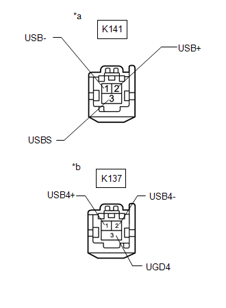
(a) Disconnect the K141 DCM (telematics transceiver) connector.
(b) Disconnect the K137 navigation ECU connector.
| (c) Measure the resistance according to the value(s) in the table below. Standard Resistance:
|
|
| NG | | REPAIR OR REPLACE HARNESS OR CONNECTOR |
|
| 6. |
CHECK DCM (TELEMATICS TRANSCEIVER) |
(a) Replace the DCM (telematics transceiver) with a new one.
Click here
(b) Clear the DTCs.
Body Electrical > Navigation System > Clear DTCs(c) Turn the engine switch off.
(d) Turn the engine switch on (IG) and wait for 90 seconds.
(e) Recheck for DTCs and check that no DTCs are output.
Body Electrical > Navigation System > Trouble CodesOK:
No DTCs are output.
| OK | |
END (DCM [TELEMATICS TRANSCEIVER] IS DEFECTIVE) |
|
| 7. |
CHECK NAVIGATION ECU |
(a) Replace the navigation ECU with a new one.
Click here
(b) Clear the DTCs.
Body Electrical > Navigation System > Clear DTCs(c) Turn the engine switch off.
(d) Turn the engine switch on (IG) and wait for 90 seconds.
(e) Recheck for DTCs and check that no DTCs are output.
Body Electrical > Navigation System > Trouble CodesOK:
No DTCs are output.
| OK | |
END (NAVIGATION ECU IS DEFECTIVE) |
| NG | | REPLACE RADIO AND DISPLAY RECEIVER ASSEMBLY
|
READ NEXT:
 Electric Throttle Malfunction (B15E5)
DESCRIPTION
DTC No. Detection Item
DTC Detection Condition Trouble Area
B15E5 Electric Throttle Malfunction
Electric throttle sensor malfunction
CAN communica
Air Conditioner ECU Vehicle Information Reading/Writing Processor Malfunction (B15F5)
DESCRIPTION This DTC may be stored when items controlled by the air conditioning amplifier assembly cannot be customized via the navigation system vehicle customization screen.
HINT: The air conditi
Main Body ECU Vehicle Information Reading/Writing Process Malfunction (B15F6)
DESCRIPTION This DTC is stored when items controlled by the main body ECU (multiplex network body ECU) cannot be customized via the navigation system vehicle customization screen.
HINT: The main bod
SEE MORE:
Telephone Sub Antenna Circuit Short to Ground (B153711,B153713)
DESCRIPTION These DTCs are stored when a malfunction occurs in the telephone and GPS antenna (for Front Side).
DTC No. Detection Item
DTC Detection Condition Trouble Area
B153711 Telephone Sub Antenna Circuit Short to Ground
Telephone antenna (sub) impedance (Ω) i
Components
COMPONENTS ILLUSTRATION
*A for RH Side
*B for LH Side
*1 NO. 1 FLOOR UNDER COVER
*2 NO. 2 FLOOR UNDER COVER
N*m (kgf*cm, ft.*lbf): Specified torque
- - ILLUSTRATION
*1 PARKING BRAKE SHOE ADJUSTING HOLE PLUG
*2 REAR A
