Toyota Camry (XV70): Telephone And Gps Antenna Cords (for Front Side)
Components
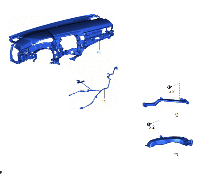
COMPONENTS
ILLUSTRATION
|
*1 | INSTRUMENT PANEL SAFETY PAD SUB-ASSEMBLY |
*2 | NO. 2 SIDE DEFROSTER NOZZLE DUCT |
|
*3 | NO. 3 HEATER TO REGISTER DUCT SUB-ASSEMBLY |
*4 | TELEPHONE AND GPS ANTENNA CORD |
Removal
REMOVAL
CAUTION / NOTICE / HINT
The necessary procedures (adjustment, calibration, initialization, or registration) that must be performed after parts are removed and installed, or replaced during telephone and GPS antenna cord removal/installation are shown below.
Necessary Procedures After Parts Removed/Installed/Replaced|
Replaced Part or Performed Procedure |
Necessary Procedure | Effect/Inoperative Function when Necessary Procedure not Performed |
Link |
|---|---|---|---|
|
Disconnect cable from negative battery terminal |
Perform steering sensor zero point calibration. |
Lane Tracing Assist System |
|
|
Pre-collision System | |||
|
Memorize steering angle neutral point |
Parking Assist Monitor System |
| |
|
Panoramic View Monitor System |
|
CAUTION:
Some of these service operations affect the SRS airbag system. Read the precautionary notices concerning the SRS airbag system before servicing.
.png)
Click here
.gif)
PROCEDURE
1. REMOVE INSTRUMENT PANEL SAFETY PAD SUB-ASSEMBLY
Click here
2. REMOVE NO. 2 SIDE DEFROSTER NOZZLE DUCT
Click here
3. REMOVE NO. 3 HEATER TO REGISTER DUCT SUB-ASSEMBLY
Click here
4. REMOVE TELEPHONE AND GPS ANTENNA CORD
(a) Disconnect the connector.
.png)
(b) Disengage the 2 claws.
(c) Disengage the 7 clamps to remove the telephone and GPS antenna cord.
Installation
INSTALLATION
PROCEDURE
1. INSTALL TELEPHONE AND GPS ANTENNA CORD
(a) Engage the 7 clamps.
(b) Engage the 2 claws.
(c) Connect the connector to install the telephone and GPS antenna cord.
2. INSTALL NO. 3 HEATER TO REGISTER DUCT SUB-ASSEMBLY
Click here
.gif)
3. INSTALL NO. 2 SIDE DEFROSTER NOZZLE DUCT
Click here
4. INSTALL INSTRUMENT PANEL SAFETY PAD SUB-ASSEMBLY
Click here
READ NEXT:
 Telephone And Gps Antenna Cords (for Roof Side)
ComponentsCOMPONENTS ILLUSTRATION
*1 TELEPHONE AND GPS ANTENNA CORD
- - RemovalREMOVAL CAUTION / NOTICE / HINT
The necessary procedures (adjustment, calibration, initializatio
Precaution
PRECAUTION PRECAUTION FOR DISCONNECTING CABLE FROM NEGATIVE BATTERY TERMINAL
NOTICE: When disconnecting the cable from the negative (-) battery terminal, initialize the following systems after the t
SEE MORE:
Settings display
◆ Changing settings
Use the meter control switches on the steering wheel to change
settings.
1. Press or
to select
.
2. Operate the switches to select a desired item.
3. Change the setting by referring to the message displayed on the
screen.
◆ Setting items
■ LTA (Lane Tracing Ass
Problem Symptoms Table
PROBLEM SYMPTOMS TABLE
HINT:
Use the table below to help determine the cause of problem symptoms. If multiple suspected areas are listed, the potential causes of the symptoms are listed in order of probability in the "Suspected Area" column of the table. Check each symptom by checking the susp
