Toyota Camry (XV70): Ultrasonic Sensor (Front Left Corner) Missing Message (C1AE187)
DESCRIPTION
This DTC is stored when an open circuit or short occurs in the communication line between the front corner ultrasonic sensor LH and the front center ultrasonic sensor LH, or when a malfunction occurs in the front corner ultrasonic sensor LH.
|
DTC No. | Detection Item |
DTC Detection Condition | Trouble Area |
|---|---|---|---|
|
C1AE187 | Ultrasonic Sensor (Front Left Corner) Missing Message |
Front corner ultrasonic sensor LH lost communication |
|
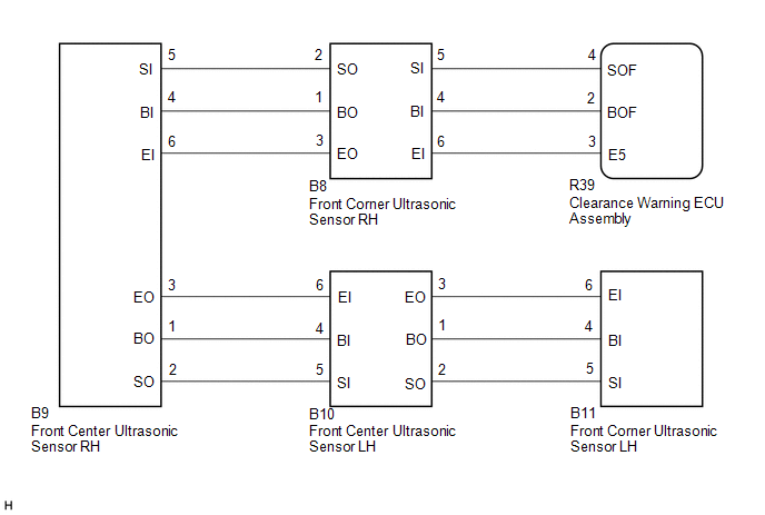
WIRING DIAGRAM
CAUTION / NOTICE / HINT
NOTICE:
- Perform registration after replacing or removing and installing the ultrasonic sensor or clearance warning ECU assembly.
Click here
.gif)
- If a DTC is detected again after the repair, turn the ignition switch to ON and turn the intuitive parking assist system on, and then clear the DTC.
Click here
- If C1AE296 is output at the same time, check C1AE296 first.
Click here
PROCEDURE
|
1. | VEHICLE CONDITION AND WORK DETAILS CHECK |
(a) Check the vehicle condition and work details.
|
Result | Proceed to |
|---|---|
|
The clearance warning ECU assembly or ultrasonic sensor has not been replaced |
A |
| The clearance warning ECU assembly or ultrasonic sensor has been replaced |
B |
| B |
.gif) | GO TO CALIBRATION |
|
.gif)
| 2. |
CHECK CONNECTOR CONNECTION CONDITION (ULTRASONIC SENSOR) |
(a) Check that the connector is properly connected to the front corner ultrasonic sensor and front center ultrasonic sensor.
|
| 3. |
CHECK FOR DTC |
(a) According to the display on the GTS, check for DTCs.
Body Electrical > Clearance Warning > Trouble Codes(b) According to the display on the GTS, clear the DTCs.
Body Electrical > Clearance Warning > Clear DTCs(c) Recheck for DTCs.
Body Electrical > Clearance Warning > Trouble Codes|
Result | Proceed to |
|---|---|
|
C1AE187 is not output |
A |
| C1AE187 is output |
B |
| A |
| END (CONNECTOR CONNECTION MALFUNCTION) |
|
| 4. |
CHECK CONNECTOR CONNECTION CONDITION (CLEARANCE WARNING ECU ASSEMBLY) |
(a) Check that the connector is properly connected to the clearance warning ECU assembly.
|
| 5. |
CHECK FOR DTC |
(a) According to the display on the GTS, check for DTCs.
Body Electrical > Clearance Warning > Trouble Codes(b) According to the display on the GTS, clear the DTCs.
Body Electrical > Clearance Warning > Clear DTCs(c) Recheck for DTCs.
Body Electrical > Clearance Warning > Trouble Codes DTC OUTPUT COMBINATION:|
Symptoms | DTC Detection | |||
|---|---|---|---|---|
|
C1AE487 | C1AE387 |
C1AE287 | C1AE187 | |
|
Symptom 1 | Not output |
Not output | Not output |
Not output |
|
Symptom 2 | Output |
Output | Output |
Output |
| Symptom 3 |
Not output | Output |
Output | Output |
|
Symptom 4 | Not output |
Not output | Output |
Output |
| Symptom 5 |
Not output | Not output |
Not output | Output |
|
Result | Proceed to |
|---|---|
|
Listed under symptom 1 in combination table |
A |
| Listed under symptom 2 in combination table |
B |
| Listed under symptom 3 in combination table |
C |
| Listed under symptom 4 in combination table |
D |
| Listed under symptom 5 in combination table |
E |
| A |
| USE SIMULATION METHOD TO CHECK
|
| B |
| GO TO CORRESPONDING FLOWCHART (INTUITIVE PARKING ASSIST SYSTEM (C1AE487)) |
| C |
| GO TO CORRESPONDING FLOWCHART (INTUITIVE PARKING ASSIST SYSTEM (C1AE387)) |
| D |
| GO TO CORRESPONDING FLOWCHART (INTUITIVE PARKING ASSIST SYSTEM (C1AE287)) |
|
| 6. |
CHECK WIRE HARNESS AND CONNECTOR (FRONT CENTER ULTRASONIC SENSOR LH - FRONT CORNER ULTRASONIC SENSOR LH) |
(a) Disconnect the B10 front center ultrasonic sensor LH connector.
(b) Disconnect the B11 front corner ultrasonic sensor LH connector.
(c) Measure the resistance according to the value(s) in the table below.
Standard Resistance:
|
Tester Connection | Condition |
Specified Condition |
|---|---|---|
|
B10-1 (BO) - B11-4 (BI) |
Always | Below 1 Ω |
|
B10-2 (SO) - B11-5 (SI) |
Always | Below 1 Ω |
|
B10-3 (EO) - B11-6 (EI) |
Always | Below 1 Ω |
|
B10-1 (BO) or B11-4 (BI) - Body ground |
Always | 10 kΩ or higher |
|
B10-2 (SO) or B11-5 (SI) - Body ground |
Always | 10 kΩ or higher |
|
B10-3 (EO) or B11-6 (EI) - Body ground |
Always | 10 kΩ or higher |
| NG | | REPAIR OR REPLACE WIRE HARNESS OR CONNECTOR |
|
| 7. |
REPLACE FRONT CORNER ULTRASONIC SENSOR LH |
(a) Replace the front corner ultrasonic sensor LH with a new or normally functioning one.
Click here
HINT:
To check if the ultrasonic sensor is functioning correctly, replace it with another ultrasonic sensor.
|
| 8. |
RECHECK FOR DTC |
(a) According to the display on the GTS, check for DTCs.
Body Electrical > Clearance Warning > Trouble Codes(b) According to the display on the GTS, clear the DTCs.
Body Electrical > Clearance Warning > Clear DTCs(c) Recheck for DTCs.
Body Electrical > Clearance Warning > Trouble Codes|
Result | Proceed to |
|---|---|
|
No DTC is output | A |
|
"C1AE187" is output | B |
| A |
| END (FRONT CORNER ULTRASONIC SENSOR LH WAS DEFECTIVE) |
| B |
| REPLACE CLEARANCE WARNING ECU ASSEMBLY |
READ NEXT:
 Ultrasonic Sensor (Front Left Corner) Component Internal Failure (C1AE196)
DESCRIPTION The front corner ultrasonic sensor LH is installed on the front bumper. The clearance warning ECU assembly detects obstacles based on signals it receives from the front corner ultrasonic s
Ultrasonic Sensor (Front Left Center) Missing Message (C1AE287)
DESCRIPTION This DTC is stored when an open circuit or short occurs in the communication line between the front center ultrasonic sensor LH and the front center ultrasonic sensor RH, or when a malfunc
Ultrasonic Sensor (Front Left Center) Component Internal Failure (C1AE296)
DESCRIPTION The front center ultrasonic sensor LH is installed on the front bumper. The clearance warning ECU assembly detects obstacles based on signals it receives from the front center ultrasonic s
SEE MORE:
Inspection
INSPECTION PROCEDURE 1. INSPECT BRAKE DISC INSIDE DIAMETER
(a) Using a brake drum gauge or an equivalent tool, measure the inside diameter of the rear disc.
Standard Inside Diameter: 173 mm (6.81 in.) Maximum Inside Diameter:
174 mm (6.85 in.) If the inside diameter is more than the ma
Fail-safe Chart
FAIL-SAFE CHART FAIL-SAFE CHART (a) When the skid control ECU (brake actuator assembly) detects a solenoid valve malfunction or abnormal signal from a sensor, the brake actuator assembly cuts power and sends a signal indicating a malfunction of the vehicle stability control system to the ECM.
HINT
